Page is loading ...

1158 WIRELESS EIGHT-ZONE
INPUT MODULE
Installation Guide
DESCRIPTION
When a DMP panel is installed in a
location with an existing non-DMP
panel, the 1158 Wireless Eight-
Zone Input Module can be used
to convert up to eight existing
normally closed, hardwired zones
into wireless zones. This allows the
new DMP panel to communicate
with existing zones.
The 1158 uses two serial numbers
to accommodate up to eight zones
and can be powered by transferring
AC and battery power from the
existing panel.
Compatibility
• All DMP 1100 Series Wireless
Receivers and burglary panels
What is Included?
• 1158 Wireless Eight-Zone Input
Module
• Hardware pack
1PROGRAM THE PANEL
The 1158 can be programmed with up to eight zones. When
programming the 1158 in the panel, refer to the panel programming
guide as needed.
Program the serial number associated with contacts 1 through 4
first. Then, start by programming contact 1.
When you enter the serial number associated with contacts
5 through 8, contact 1 displays again indicating that you are
programming the first contact associated with that serial number.
1. In ZONE INFORMATION, enter the zone number, and then
press CMD.
2. Enter the ZONE NAME and press CMD.
3. Once ZONE TYPE appears, select the appropriate zone type,
and then press CMD.
4. At the NEXT ZONE prompt, select NO. If you see the
WIRELESS ZONE prompt, select YES.
Note: If you are programming the 1158 onto a zone that can
be either hard wired or wireless, this prompt appears. If the
zone is wireless-only, this prompt does not appear.
5. Enter the eight-digit SERIAL NUMBER and press CMD.
6. Enter the CONTACT number being used.
7. Enter the SUPERVSN TIME and press CMD.
8. At the NEXT ZONE prompt, select YES and continue to
program up to seven more zones.
Note: Zones on the same serial number must be entered
sequentially.
Figure 1: 1158
PANEL ZONES
XT30/XT50,
XTLplus,
& XTLtouch
The zone numbers begin with the 1158
address and are followed by the particular
zone from the 1158. For example, an 1158 at
keypad address 4 would provide zones 41,
42, 43, and 44.
XR150 Zone numbers are valid from 500-
599. Zones must still be programmed
sequentially (i.e. 551, 552, 553, and 554).
XR550 Zone numbers are valid from 500-
999. Zones must still be programmed
sequentially (i.e. 551, 552, 553, and 554).

2 1158 INSTALLATION GUIDE | DIGITAL MONITORING PRODUCTS
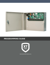
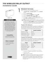
Figure 2: 1158 Mounting Hole Locations
Mounting
Hole
Mounting
Hole
Mounting
Hole
Wire the contacts and connect the receiver before connecting power to the 1158.
1. Locate the existing normally closed contacts you would like to connect to the 1158. These contacts
should be within 2,500 feet of the 1158.
2. Use the existing wire to connect a contact to a zone terminal and a ground (GND) terminal. See
Figure2.
3. Repeat step2 for the remaining contacts, as needed.
Note: When wiring new contacts, EOL resistors do not need to be used. However, if existing contacts
have EOL resistors installed, they do not need to be changed or removed. Use 18to 22 gauge wire for
all new contacts.
4. Connect the positive and negative DC OUTPUT terminals on the 1158 to any devices that require
separate power, if necessary.
Note: The 1158 can provide up to 150mA of current to powered devices that require 12V power. When
adding powered devices, calculate the total current draw.
4WIRE THE 1158 ZONES
3MOUNT THE 1158
Place the 1158 close to the existing non-DMP panel.
With the housing cover removed, use the supplied screws to secure the 1158 to a wall or other flat surface. Use
the built-in holes on the PCB to screw the housing base onto a surface without removing the PCB.
See Figure 2.
Use an 1106 Universal Wireless Transmitter to determine the location of the 1158.
The 1106 provides a Survey LED capability to allow one person to confirm communication with the wireless
receiver or panel while the cover is removed.
1. Hold the 1106 in the exact desired location.
2. Press the tamper switch to send data to the panel and determine if communication is confirmed or
faulty.
Confirmed: If communication is confirmed, for each press or release of the tamper switch the LED
blinks immediately on and immediately o. Repeat this test to confirm five separate consecutive LED
blinks. Any indication otherwise means proper communication has not been established.
Faulty: If communication is faulty, the LED remains on for about 8 seconds or flashes multiple times in
quick succession. Relocate the transmitter or receiver until the LED confirms clear communication.
SELECT A LOCATION
2

1158 INSTALLATION GUIDE | DIGITAL MONITORING PRODUCTS 3
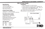
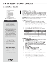
Figure 3: 1158 Zone and Power Wiring
To Zones
To Powered
Devices
To Backup Bat-
tery or 12VDC
Power
To 16.5VAC
Power
The 1158 can be powered by either AC or DC power sources. Follow the instructions below to transfer AC
power from an existing panel or connect an AC transformer, DC transformer, or backup battery to the 1158.
Option A: Connect AC Power
To power the 1158, you can transfer AC power from the existing panel to the 1158. You can also use a DMP
Model 321 40VA, 16.5VAC Plug-In Transformer to power to 1158. If a backup battery is attached to the
existing panel, it can be transfered to the 1158 as well. Use 18-22gauge wire for all wiring connections.
1. Connect the 1158’s AC power terminals to the existing panel’s 16.5VAC power supply. See Figure3.
2. Ensuring that polarity is correct, connect the positive and negative BAT terminals on the 1158 to the
existing panel’s backup battery, if necessary. The battery charging circuit supplies up to 50mA.
Note: A Battery Trouble message will not be generated if a backup battery is not connected to the
1158.
3. Snap the housing cover into place.
5POWER THE 1158
Option B: Connect DC Power
You can also use a 376L 12VDC 600mA Plug-in Power Supply or other 12VDC power source with the 1158.
Note: An AC Trouble message will not be generated if the 1158 is not connect to an AC power source.
1. Connect the 376L flying leads to the BAT terminals on the 1158. See Figure 3.
2. Plug the 376L into a standard electrical outlet.

Designed, engineered, and
manufactured in Springfield, MO
using U.S. and global components.
LT-1642 22164
1158 WIRELESS
EIGHT-ZONE
INPUT MODULE
Specifications
Frequency Range 905-924 MHz
Dimensions 4.65” L x 3.10” W x 1.40” H
11.81 L x 7.87 W x 3.56 H cm
Color White
Housing Material Flame Retardant ABS
Current Draw
DC Output 150 mA
Battery Charge 50 mA
Patents
U.S. Patent No. 7,239,236
Compatibility
XT30 panels with 1100D Series Wireless Receiver with Version
105 or higher
XT50 panels with integrated wireless receiver or 1100D Series
Wireless Receiver with Version 105 or higher
XR150/XR550 Series panels with 1100X Series Wireless
Receivers with Version 105 or higher
XTLplus panels with integrated wireless receiver
XTLtouch panels with integrated wireless receiver
Certifications
FCC Part 15 Registration ID CCKPC0101
IC Registration ID 5251A-PC0101
INTRUSION • FIRE • ACCESS • NETWORKS
2500 North Partnership Boulevard
Springfield, Missouri 65803-8877
800.641.4282 | DMP.com
FCC INFORMATION
This device complies with Part 15 of the FCC Rules. Operation is subject to the following two conditions:
1. This device may not cause harmful interference, and
2. This device must accept any interference received, including interference that may cause undesired operation.
The antenna used for this transmitter must be installed to provide a separation distance of at least 20 cm (7.874 in.) from
all persons. It must not be located or operated in conjunction with any other antenna or transmitter.
Changes or modifications made by the user and not expressly approved by the party responsible for compliance could
void the user’s authority to operate the equipment.
Note: This equipment has been tested and found to comply with the limits for a Class B digital device, pursuant to
part 15 of the FCC Rules. These limits are designed to provide reasonable protection against harmful interference in
a residential installation. This equipment generates, uses and can radiate radio frequency energy and, if not installed
and used in accordance with the instructions, may cause harmful interference to radio communications. However,
there is no guarantee that interference will not occur in a particular installation. If this equipment does cause
harmful interference to radio or television reception, which can be determined by turning the equipment o and on,
the user is encouraged to try to correct the interference by one or more of the following measures:
1. Reorient or relocate the receiving antenna.
2. Increase the separation between the equipment and receiver.
3. Connect the equipment into an outlet on a circuit dierent from that to which the receiver is connected.
4. Consult the dealer or an experienced radio/TV technician for help.
INDUSTRY CANADA INFORMATION
This device complies with Industry Canada Licence-exempt RSS standards. Operation is subject to the following two conditions:
1. This device may not cause interference, and
2. this device must accept any interference, including interference that may cause undesired operation of the device.
This system has been evaluated for RF Exposure per RSS-102 and is in compliance with the limits specified by Health Canada Safety
Code 6. The system must be installed at a minimum separation distance from the antenna to a general bystander of 7.87 inches (20 cm)
to maintain compliance with the General Population limits.
Le présent appareil est conforme aux CNR d’Industrie Canada applicables aux appareils radio exempts de licence. L’exploitation est
autorisée aux deux conditions suivantes:
1. l’appareil ne doit pas produire de brouillage, et
2. l’utilisateur de l’appareil doit accepter tout brouillage radioélectrique subi, même si le brouillage est susceptible d’en
compromettre le fonctionnement.
L’exposition aux radiofréquences de ce système a été évaluée selon la norme RSS-102 et est jugée conforme aux limites établies par le
Code de sécurité 6 de Santé Canada. Le système doit être installé à une distance minimale de 7.87 pouces (20 cm) séparant l’antenne
d’une personne présente en conformité avec les limites permises d’exposition du grand public.
© 2022
/