Page is loading ...

INSTALLATION GUIDE
XTLN-WIFI PANEL

MODEL XTLN-WiFi
INSTALLATION GUIDE
FCC NOTICE
This equipment has been tested and found to comply with the limits for a Class B digital device, pursuant
to part 15 of the FCC Rules. These limits are designed to provide reasonable protection against harmful
interference in a residential installation. This equipment generates, uses and can radiate radio frequency
energy and, if not installed and used in accordance with the instructions, may cause harmful interference
to radio communications. However, there is no guarantee that interference will not occur in a particular
installation. If this equipment does cause harmful interference to radio or television reception, which can be
determined by turning the equipment off and on, the user is encouraged to try to correct the interference
by one or more of the following measures:
• Reorient or relocate the receiving antenna.
• Increase the separation between the equipment and receiver.
• Connect the equipment into an outlet on a circuit different from that to which the receiver is
connected.
• Consult the dealer or an experienced radio/TV technician for help.
Changesormodicationsnotexpresslyapprovedbythepartyresponsibleforcompliancecouldvoidthe
user’s authority to operate the equipment.
This device has been designed to operate with the integrated 1100 Series PCB antenna having a maximum
gain of 1.8 dB. Antennas having a gain greater than 1.8 dB are strictly prohibited for use with this device.
The required antenna impedance is 50 ohms.
If necessary, the installer should consult the dealer or an experienced radio/television technician
foradditionalsuggestions.Theinstallermayndthefollowingbooklet,preparedbytheFederal
Communications Commission, helpful:
“How to identify and Resolve Radio-TV Interference Problems.”
ThisbookletisavailablefromtheU.S.GovernmentPrintingOfce,WashingtonD.C.20402
StockNo.004-000-00345-4
©2013DigitalMonitoringProducts,Inc.
InformationfurnishedbyDMPisbelievedtobeaccurateandreliable.
This information is subject to change without notice.

XTLN-WiFi Installation Guide Digital Monitoring Products
i
TABLE OF CONTENTS
Panel Specications
1.1 Power Supply .........................................1
1.2 Communication .......................................1
1.3 Keypads .................................................1
1.4 Number of Zones ....................................1
1.5 EnclosureSpecications ..........................1
Introduction
2.1 SystemCongurations .............................1
2.2 Caution Notes .........................................1
2.3 Compliance Instructions ..........................1
System Components
3.1 Accessory Devices ...................................2
Installation
4.1 MountingLocationInformation ................3
4.2 MountingtheEnclosure ...........................3
Primary Power Supply
5.1 DC Input ................................................3
Secondary Power Supply
6.1 Standby Battery ......................................4
6.2 Replacement ..........................................4
6.3 Battery Supervision .................................4
LED Operation
7.1 BacklitLogo ............................................5
On-Board WiFi Network
8.1 Description .............................................5
8.2 WiFiLEDs ...............................................5
Reset Button
9.1 Description .............................................5
Programming Connection
10.1 ProgrammingConnection ........................5
On-Board 1100 Series Wireless
11.1 Wireless Antenna ....................................5
11.2 WirelessLEDOperation ...........................5
Keypads
12.1 MountingKeypads ..................................6
12.2 InstallationSpecications ........................6
12.3 Wireless Keypad Association ....................6
Wireless Zones
13.1 Description .............................................6
Wireless Key Fobs and Outputs
14.1 Description .............................................6
Flash Load Button
15.1 Description ............................................7
Listed Compliance Specications
16.1 Introduction ...........................................7
16.2 UseMarking ...........................................7
16.3 NFPA 72 .................................................7
16.4 TypesOfService .....................................7
16.5 Bypass Reports .......................................7
16.6 Battery Standby ......................................7

Digital Monitoring Products XTLN-WiFi Installation Guide
ii
TABLE OF CONTENTS
Household Burglar-Alarm System Units
ANSI/UL 1023
17.1 Bell Cutoff ..............................................7
17.2 Entry Delay ............................................7
17.3 Exit Delay ...............................................7
17.4 Wireless External Contact ........................7
17.5 Wireless Supervision Time .......................7
17.6 Wireless Audible Annunciation .................8
17.7 Panel location .........................................8
17.8 Test Frequency .......................................8
Central Station Burglar Alarm Units
ANSI/UL 1610
18.1 Supervision ............................................8
18.2 Remote Disarm .......................................8
18.3 Central Station ........................................8
Household Fire Warning System
ANSI/UL 985 NFPA 72 Specications
19.1 BellOutputDenition ..............................8
19.2 HouseholdSystem ..................................8
19.3 Wireless External Contact ........................8
19.4 Wireless Supervision Time .......................8
19.5 Test Frequency .......................................8
19.6 Wired Modules ........................................8
Listings and Approvals .......................... 10

XTLN-WiFi Installation Guide Digital Monitoring Products
1
PANEL SPECIFICATIONS
Panel Specications
1.1 Power Supply
Input: 12VDC
StandbyBattery: 3.7VDCLithium
All circuits inherent power limited
1.2 Communication
Built-innetworkcommunicationtoDMPModelSCS-1RorSCS-VRReceivers.
1.3 Keypads
Youcanconnectupto4alphanumeric7800SeriesGraphicTouchscreenKeypadsor9000SeriesWireless
Keypads.
1.4 Number of Zones
• XTLN-WiFihas28wirelessinitiatingzonesnumbered1-28
• ZoneandOutputnumbers31to34and41to44cansupport1100SeriesKeyFobs,OutputModules,
or sirens
1.5 Enclosure Specications
TheXTLN-WiFipanelshipsinaplasticenclosurewithauser’sguideandprogrammingsheet.
Size Color
5.5”Wx3.75”Hx1”D White(W)
Introduction
2.1 System Congurations
The panel can be programmed to operate as any of the following system types:
• All/Perimetersystemthatprovidesoneperimeterareaandoneinteriorarea
• Home/Sleep/Awaysystemthatprovidesoneperimeter,oneinterior,andonebedroomarea.The
bedroom area provides for any protection devices the user wants disarmed during their sleeping hours
and armed in the Away mode.
• Sixareasystemthatprovidesareasofprotectionthatcanbeindependentlyarmedordisarmed.
2.2 Caution Notes
Throughoutthisguideyouwillseecautionnotescontaininginformationyouneedtoknowwheninstalling
thepanel.Thesecautionsareindicatedwithayieldsign.Wheneveryouseeacautionnote,makesureyou
completely read and understand its information. Failing to follow the caution note can cause damage to the
equipment or improper operation of one or more components in the system.
2.3 Compliance Instructions
ForapplicationsthatmustconformtoalocalauthoritiesinstallationstandardoraNationalRecognized
TestingLaboratorycerticatedsystem,pleaseseetheListedComplianceSpecicationssectionneartheend
of this guide for additional instructions.
INTRODUCTION

Digital Monitoring Products XTLN-WiFi Installation Guide
2
SYSTEM COMPONENTS
System Components
3.1 Accessory Devices
DMP Two-Way Wireless Devices
1100R Repeater Provides additional range for wireless devices.
1101UniversalTransmitter Provides both internal and external contacts that may be used at the same time to yield two
individualreportingzonesfromonewirelesstransmitter.
1102UniversalTransmitter Provides one external contact.
1103UniversalTransmitter Provides both and internal and external contacts that may be used at the same time to
yieldtwoindividualreportingzonesfromonewirelesstransmitter.RequiresEOLresistorfor
external contact.
1105UniversalTransmitter Provides both internal and external contacts that may be used at the same time to yield two
individualreportingzonesfromonewirelesstransmitter.
*1107MicroWindowTransmitter Provides a wireless window transmitter
*1114Four-ZoneExpander ProvidesfourwirelesszoneswithEOLresisters.
*1116RelayOutput Provides one Form C relay.
*1117LEDAnnunciator Provides a visual system status indicator.
*1119DoorSounder Provides a wireless sounder with integrated door contact
*1121PIRMotionDetector Provides motion detection with pet immunity.
1125PIRMotionDetector
Providesmultiplelenscongurations,dualcoverageareaselection,andsensitivityadjustments.
*1126C/1126R/1126WPIRMotion
Detector
CeilingmountmotiondetectorwithpanelprogrammablesensitivityandDisarm/Disable
functionality.
1127C/1127WPIRMotion
Detector
WallmountmotiondetectorwithpanelprogrammablesensitivityandDisarm/Disable
functionality.
*1129GlassbreakDetector Detectstheshatteringofframedglassmountedinanoutsidewallandprovidesfull-pattern
coverage and false-alarm immunity.
*1131RecessedContact
Provides concealed protection for doors, windows or other applications.
1135/*1135DBWirelessSirens Provides a wireless siren
*1139BillTrap Provides a silent alarm option for use in cash drawers.
1142BCTwo-buttonPanicBelt
Clip Transmitter
Provides portable two-button panic operation.
1142Two-buttonPanicTransmitter
Provides permanently mounted under-the-counter two-button panic operation.
*1145-4(Four-Button)
*1145-2(Two-Button)
*1145-1(One-Button)
KeyFobtransmittersdesignedtoclipontoakeyringorlanyard.
1161ResidentialSmokeDetector Residentialsmokedetectorwithsounder.
1162ResidentialSmokeDetector Residentialsmoke/heatdetectorwithsounderandxedrate-of-riseheatdetector.
1183-135FHeatDetector Fixed temperature heat detector
1183-135RHeatDetector Fixed temperature and rate-of-rise heat detector
*1184CarbonMonoxideDetector CarbonMonoxidedetector.
Interface Module
*738ZZ-WaveInterfaceModule ProvidesconnectionforZ-Wavemodules.
Keypads
7800SeriesLCDkeypads Allowsyoutocontrolthepanelfromvariousremotelocations.Connectuptofour7872or
7873keypadstothekeypadbususingterminals7,8.9,and10.
9000SeriesLCDkeypads Allowsyoutocontrolthepanelfromvariousremotelocationsusing9000SeriesWireless
Keypads.
* These devices have not been investigated and shall not be used in listed installations

XTLN-WiFi Installation Guide Digital Monitoring Products
3
INSTALLATION
Installation
4.1 Mounting Location Information
A location should be selected that is centrally located between the 1100 Series transmitters used in the
installation.InstalltheXTLN-WiFiawayfrommetalobjects.MountingtheXTLN-WiFionornearmetal
surfacesimpairsperformance.Whenselectingthepropermountinglocationofatransmitter,refertothe
LEDSurveyOperationsectionofthespecicinstallationguideforthetransmitterbeinginstalled.
4.2 Mounting the Enclosure
TheenclosurefortheXTLN-WiFipanelmustbemountedusingtheprovided#6screwsinthefourmounting
holesshowninFigure2.Mounttheenclosureinasecure,dryplaceawayfrommetalobjectstoprotect
thepanelfromdamageduetotamperingortheelements.Mountthepanelaminimumof4feetfromany
wireless transmitters or repeaters. It is not necessary to remove the PCB when installing the enclosure.
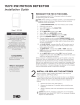
Mounting Hole Locations
WiFi Network
Module
Figure 1: Mounting Hole Locations
Primary Power Supply
5.1 DC Input
MounttheXTLN-WiFipanelnearawalloutletfortheModel372-500plug-inDCpowersupply.Inaddition
topoweringthepanel,theDCplug-inpowersupplyalsochargestheback-upbattery.The372-500mustbe
locatedwithin100feetofthepanelusing22AWGwire.Usethefollowingstepstoconnecttheplug-inpower
supply:
OBSERVE POLARITY
1.Using22AWGwire,connectthepanelPWR(J2)rstterminal(+)tothepositiveterminalonthe
power supply.
2.ConnectthepanelPWR(J2)secondterminal(-)tothenegativeterminalonthepowersupply.
3.Plugthepowersupplyintoa120VoltAC,60Hzdedicatedoutletnotcontrolledbyaswitch.
Wire Exits for DC
Power Supply
+
Model 372-500
DC Plug-in
Power
Supply
Use 22 AWG for
Power Supply connection
_
J2
Figure 2: DC Power Supply Connection

Digital Monitoring Products XTLN-WiFi Installation Guide
4
INSTALLATION
Secondary Power Supply
6.1 Standby Battery
TheXTLN-WiFirechargeablebatteryisusedtoprovidebackupbatterypowerwhenDCpowerisnot
available.ThebatteryisintendedforbackuppoweronlyandnottooperatetheXTLN-WiFipanelonadaily
basis.Ifthebatteryislow,ornotpluggedintotheJ7batteryconnector,alowbatteryconditionisindicated
bytheXTLN-WiFipanel.
Note:IfremovingtheXTLN-WiFipanelfromservice,disconnectthebackupbatteryfromtheXTLN-WiFiJ7
connector.
6.2 Replacement
UsethefollowingstepstoreplacetheXTLN-WiFistandbybattery.DMPrecommendsreplacingthebattery
every3yearsundernormaluse.
1. Unplugthebatteryconnector(J7)fromtheXTLN-WiFipanel.
2. Ifinstalled,removethescrewfromthePCB.
3. LoosenthetopPCBsnaps.
4. LeanthepanelPCBforwardandliftoutfromthebottomPCBsnaps.
5. Remove and properly dispose of the used battery.
Caution:Riskofre,explosion,andburns.Donotdisassemble,heatabove212°F(100°C),
or incinerate. Properly dispose of used batteries.
6. PlacethenewbatteryintotheXTLN-WiFihousingbasewiththebatterywiresdirectedtowardthe
bottomrightcorner.SeeFigure4.
7. SettheXTLN-WiFiPCBintothebottomsnapsandpressintothetopsnapstosecureinplace.
8. Plugthebatteryintothepanelconnector(J7).
6.3 Battery Supervision
ThepanelteststhebatteryonceeveryhourwhenDCpowerispresent.Thistestoccurs15minutespast
eachhourandlastsforveseconds.Aloadisplacedonthebatteryandifthebatteryvoltageislow,alow
batteryisdetected.IfDCpowerhasfailed,alowbatteryisdetectedanytimethebatteryvoltagefalls
below3.7V.
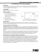
PCB Screw Location
Top PCB Snaps
Bottom PCB Snaps Battery
connector
3.7V
Rechargeable
Battery
Figure 4: Standby Battery ReplacementFigure 3: PCB Screw Location

XTLN-WiFi Installation Guide Digital Monitoring Products
5
INSTALLATION
LED Operation
7.1 Backlit Logo
ThebacklitlogoindicatesthePowerandArmedstatusofthepanel.Dependingontheoperation,theLED
displaysinRedorGreenaslistedinthetable.
Color and Activity Operation
GreenSteady PanelDisarmed,PrimaryPowerOK,BatteryOK
GreenBlinking PanelDisarmed,PrimaryPowerOK,BatteryFault
NoLight PanelDisarmed,PrimaryPowerFault,BatteryOK
Red Steady PanelArmed,PrimaryPowerOK,BatteryOK
Red/GreenAlternate PanelArmed,PrimaryPowerOK,BatteryFault
RedBlinking PanelArmed,PrimaryPowerFault,BatteryOK
On-Board WiFi Network
8.1 Description
TheXTLN-WiFiconnectsdirectlytoaWiFinetworkforencryptedTCPcommunicationusingaWireless-B/G
connection.TheXTLN-WiFiuseswireless802.11b/gWiFitechnology,whichcantravel125ft.indoorsandcan
reachoutto460ft.outdoorswithaclearlineofsight.
Note:RangeforWiFicommunicationhasnotbeeninvestigatedbyUL.
8.2 WiFi LEDs
ThetwoWiFiLEDs,locatedinthecenterofthecircuitboard,indicatenetworkoperation.TheleftWiFi-1
LEDisagreenlightthatissolidwhenthenetworkisconnectedandblinksonandoffwhenthereisno
networkconnectivity.TherightWiFi-2LEDisayellowlightandblinkswhenmessagesarebeingreceivedor
transmitted.
Reset Button
9.1 Description
Theresetbutton(S1)islocatedontherightsideofthecircuitboardandisusedtoresettheXTLN-WiFi
microprocessor. To reset the panel prior to reprogramming, press the reset button without powering down
thesystem.Afterresettingthepanel,beginprogrammingwithin30minutes.Ifyouwaitlongerthan30
minutes, you must reset the panel again.
Programming Connection
10.1 Programming Connection
Alocking4-pinheader(PROG)isprovidedtoconnectakeypadwhenusingaDMPModel330Programming
Cable.ThisprovidesaquickandeasyconnectionforprogrammingtheXTLN-WiFipanel.Afterprogramming
iscomplete,removethekeypad.
On-Board 1100 Series Wireless
11.1 Wireless Antenna
TheXTLN-WiFiWirelessAntennaisintegratedintothecircuitboard.TheXTLN-WiFibuilt-inwirelessreceiver
operateswithDMP1100Seriestransmitters.Seesection3.1foralistofaccessorydevices.
11.2 Wireless LED Operation
Green (TX):ThegreenLEDasheseverytimethereceivertransmits(32timespersecond).Ifthepanel
isreset,orthepanelispoweredoff,thegreenLEDisoff.Undernormaloperation,thegreenLEDashes
constantly with no interruption or change.
Yellow (RX):TheyellowLEDasheseverytimetheXTLN-WiFireceivesamessagefromaprogrammed
wirelesstransmitter.Whenamessageissentbyatransmitter,typicallybypressingorreleasingthetamper
switch,theyellowLEDshouldashindicatingthattheXTLN-WiFireceivedamessagefromthetransmitter.
IftheLEDneverashes,thetransmitterisnotgettingthroughtotheXTLN-WiFi.Thiscouldbebecause
ofamisprogrammedserialnumberorthetransmitteristoofaraway.Undernormaloperation,theyellow
LEDashesateverytripofeverywirelesstransmitterandwhenthetransmittersperformtheirperiodic
check-in.ItisnotunusualforthisLEDtostayoffformanyminutesatatimewhennotransmittersare
communicating.

Digital Monitoring Products XTLN-WiFi Installation Guide
6
INSTALLATION
Keypads
12.1 Mounting Keypads
DMPkeypadshaveremovablecoversthatallowthebasetobemountedonawall,deskstandorotherat
surface using the screw holes provided on each corner.
12.2 Installation Specications
Severalfactorsdeterminetheperformancecharacteristicsofthekeypadbus:thelengthofwireused,the
numberofdevicesconnected,andthevoltageateachdevice.Whenplanningakeypadbusinstallation,
keepinmindthefollowingfourspecications:
1. DMPrecommendsusing18or22-gaugeunshieldedwireforallkeypadcircuits.Donotusetwisted
pairorshieldedwireforkeypadbusdatacircuits.
2. Onkeypadbuscircuits,tomaintainauxiliarypowerintegritywhenusing22-gaugewiredonot
exceed500feet.Whenusing18-gaugewiredonotexceed1,000feet.Toincreasethewirelength
or to add devices, install an additional power supply.
Note:Eachpanelallowsaspecicnumberofsupervisedkeypads.Addadditionalkeypadsinthe
unsupervisedmode.Refertothepanelinstallationguideforthespecicnumberofsupervised
keypadsallowed.
3. Maximumdistanceforanyonebuscircuit(lengthofwire)is2,500feetregardlessofthewire
gauge. This distance can be in the form of one long wire run or multiple branches with all wiring
totalingnomorethan2,500feet.Aswiredistancefromthepanelincreases,DCvoltageonthe
wire decreases.
4. Maximumvoltagedropbetweenthepanel(orauxiliarypowersupply)andanydeviceis2.0VDC.If
the voltage at any device is less than the required level, add an auxiliary power supply at the end
ofthecircuit.Whenvoltageistoolow,thedevicescannotoperateproperly.
Foradditionalinformationrefertothe710InstallationSheet(LT-0310)andortheLX-Bus/KeypadBusWiring
ApplicationNote(LT-2031).
12.3 Wireless Keypad Association
EnableWirelessKeypadAssociationoperationonboththekeypadandpanel.
Toenableassociationoperationinthekeypad,accesstheInstallerOptionsMenu(3577(INST)CMD).The
keypadlogoLEDsturnoffuntilassociationissuccessful.
Toenableassociationoperationinthepanel,presstheXTLN-WiFiRESETbutton3timeswithin12seconds
allowing3secondsbetweeneachpressoftheresetbutton.Wheninkeypadassociation,theXTLN-WiFiRed
andGreenlogoLEDsturnonsteady.
For60secondsthepanellistensforwirelesskeypadsthatareintheInstallerOptionsMenu(3577CMD)and
havenotbeenprogrammed,orassociatedintoanotherpanel.Thosekeypadsareassignedtotherstopen
devicepositionautomaticallybasedupontheorderinwhichtheyaredetected.ThekeypadlogoturnsGreen
to indicate it has been associated with the panel.
Wireless Zones
13.1 Description
XTLN-WiFipanelsprovide28wirelesszonesnumbered1to28.Adefaultzonename,zonetype,andarea
assignmentaredescribedintheXTLN-WiFiProgrammingGuide(LT-1237)andcanbechangedinZone
Information programming as needed. The defaults are provided as a programming convenience to help
reduce installation time.
Wireless Key Fobs and Outputs
14.1 Description
XTLN-WiFipanelsprovide8wirelesskeyfoboroutputaddressesnumbered31to34and41to44.Adefault
name is provided as a programming convenience to help reduce installation time. The default names are
describedintheXTLN-WiFiProgrammingGuide(LT-1237)andcanbechangedinOutputInformationorZone
Information programming as needed.

XTLN-WiFi Installation Guide Digital Monitoring Products
7
INSTALLATION
Flash Load Button
15.1 Description
TheXTLN-WiFipanelsoftwarecanbeupdatedviathepanel’sprogramming(PROG)header.Toupdatethe
panel with a new software version, complete the following steps at the protected premise:
1. ConnectaDMP399CablefromtheProgrammingHeadertotheserialportofyourPCoperating
RemoteLinkandcontainingtheXTLN-WiFiRemoteUpdatele.
2. StartRemoteLinkandcreateoropentheXTLN-WiFicontrolpanelaccountthatmatchesthepanel
to be updated.
3. SettheConnectionInformationTypetoDirectwithabaudrateof38400andchoosethe
appropriateCOMport.
4. SelectPanel>RemoteUpdate,thenselectthecorrectRUlefortheXTLN-WiFipanel.
5. PressandholdtheLOADbutton(S2),thenpressandreleasetheRESETbutton.
6. ReleasetheLOADbuttonandclick<Update>inRemoteLink.
7. Afterthesoftwareupdateiscompleted,removethe399cableandpresstheRESETbuttonto
resume normal panel operation.
Listed Compliance Specications
16.1 Introduction
Theprogrammingandinstallationspecicationscontainedinthissectionmustbecompletedwheninstalling
theXTLN-WiFiinaccordancewithanyoftheANSI/ULorSIAburglarystandards.Additionalspecicationsmay
be required by a particular standard.
16.2 Use Marking
CommercialCentralStation,HouseholdBurglarandFireControlUnit.
16.3 NFPA 72
ThisequipmentshouldbeinstalledinaccordancewithChapter11oftheNationalFireAlarmCode,ANSI/
NFPA72-2002,(NationalFireProtectionAssociation,BatterymarchPark,Quincy,MA02269).Printed
information describing proper installation, operation, testing, maintenance, evacuation planning, and repair
serviceistobeprovidedwiththisequipment.Warning:Owner’sinstructionnotice,nottoberemovedby
anyone except occupant.
16.4 Types Of Service
SuitableforCentralStation.SuitableforHouseholdFireandHouseholdBurglary.Testweekly.
16.5 Bypass Reports
ThebypassreportsmustbeprogrammedasYESforalllistedburglaryapplications.
16.6 Battery Standby
TheXTLN-WiFiisshippedwithabatteryfor24hourbatterystandbyoperation.
Household Burglar-Alarm System Units
ANSI/UL 1023
17.1 Bell Cutoff
Thebellcutofftimecannotbelessthan4minutes.
17.2 Entry Delay
Themaximumentrydelayusedmustnotbemorethan45seconds.
17.3 Exit Delay
The maximum exit delay used must not be more than 60 seconds.
17.4 Wireless External Contact
Whenused,theExternalContactof1101,1102,or1105transmittersmustbeprogrammedNormallyClosed.
17.5 Wireless Supervision Time
TheZoneInformationSupervisionTimecannotbesetto0(zero).

Digital Monitoring Products XTLN-WiFi Installation Guide
8
INSTALLATION
17.6 Wireless Audible Annunciation
TheWirelessAudibleoptionmustbeselectedasDAYforresidentialapplications.
17.7 Panel location
Mountpanelinsideprotectedarea.
17.8 Test Frequency
TheTestFrequencyoptionmustbeprogrammedtosendareportatleastonceevery30days.
Central Station Burglar Alarm Units
ANSI/UL 1610
18.1 Supervision
CommercialBurglaryisprovidedwhentheCellCheck-inandFailTimetimeissetto3minutes.
Note:TheSecureComWirelesstextplanselectedforthepanelshouldmatchorexceedtheprogrammed
MonthlyLimitoradditionalcellularchargesmayapply.
18.2 Remote Disarm
REMOTEDISARMmustbeprogrammedasNO.
18.3 Central Station
MESSAGETOTRANSMITprogrammingforzonesmustnotbesettoLOCAL(L).
Household Fire Warning System
ANSI/UL 985 NFPA 72 Specications
19.1 Bell Output Denition
ThewirelesssirenoftheXTLN-WiFipanelmustbeprogrammedtooperatesteadyonburglaryalarmsand
temporalonrealarms.SeetheXTLN-WiFiProgrammingGuide(LT-1237).
19.2 Household System
An alarm sounding device must be installed indoors so that it is clearly heard in all sleeping areas.
19.3 Wireless External Contact
Whenused,theExternalContactof1101,1102,or1105mustbeprogrammedNormallyClosed.Seethe
XTLN-WiFiProgrammingGuide.
19.4 Wireless Supervision Time
TheZoneInformationSupervisionTimemustbe3minutesforredevices.SeetheXTLN-WiFiProgramming
Guide.
19.5 Test Frequency
TheTestFrequencyoptionmustbeprogrammedtosendareportatleastonceevery30days.
19.6 Wired Modules
ModulesthatconnecttothePROGheader,suchasthe738Z,mustnotbeusedsincethebatterystandby
timewillbereducedbelowthe24hourminimum.

Thispageintentionallyleftblank

LT-1236 1.01 © 2013 Digital Monitoring Products, Inc.
800-641-4282
www.dmp.com
Designed,Engineeredand
AssembledintheUSA
INTRUSION•FIRE•ACCESS•NETWORKS
2500NorthPartnershipBoulevard
Springfield,Missouri65803-8877
13225
Listings and Approvals
ANSI/SIACP-2010FalseAlarmReduction
FCCWiFiModuleApprovals
FCCID:XM5-SM2144SMT
IndustryCanada:8516A-SM2144SMT
FCCWirelessApprovals
FCCPart15ID:CCKPC0117
IndustryCanada:5251A-PC0117
UnderwritersLaboratories(UL)Listed
ANSI/UL985 HouseholdFireWarning
ANSI/UL1023 HouseholdBurglar
ANSI/UL1610 CentralStationBurglar
/