Page is loading ...

XT SERIES WIRELESS INSTALLATION QUICK START GUIDE
LT-1289 20171 © 2020 Digital Monitoring Products, Inc.
2. INSTALL THE ENCLOSURE
Select a Location
Choose a location that is away from metal and electrical equipment. If
you choose to use the XT50 with built-in wireless receiver make sure to
locate the control panel where the receiver will have a clear path between
the panel and wireless transmitters. Do not place the panel with built-in
receiver in an area where the receiver will have poor signal reception from
the wireless transmitters. Make sure to walk test and survey the system
prior to mounting the control panel.
Mount the Enclosure
Prior to mounting and as needed, open any enclosure knockouts. Mount
the 340 or 349 Enclosure in a secure, dry place to protect the components
from damage due to tampering or the elements. It is not necessary to
remove the pre-mounted components when installing the enclosure. Make
sure all wiring in the XT30 or XT50 Control Panel Enclosure is routed
neatly and securely to keep the wiring o of the panel and power supply
components.
3. BATTERY CONNECTION
The control panel comes with a red and black battery harness. Connect the
positive (red) battery lead to terminal 3 and the negative (black) battery
lead to terminal 4. Do not reverse polarity as this will cause panel damage.
Terminal 4 is also used for the panels Cold Water Earth Ground.
Caution: Observe polarity.
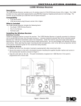
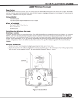
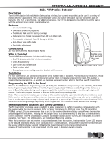
4. CONNECT WIRELESS ANTENNA TO PANEL
The XT50 Wireless Antenna terminal block is located at the top right corner
of the circuit board. The antenna installs through a small opening in the top
of the enclosure and is attached to the panel using the right terminal. The
left terminal is not used.
1. SYSTEM INFORMATION
Before installing any equipment, complete the following section.
Account Number _____________________________________________
Address ____________________________________________________
Phone Number _______________________________________________
Panel IP Address ______________________________________________
Gateway IP Address ___________________________________________
Subnet Mask _________________________________________________
Programming Port ____________________________________________
Installation Date ______________________________________________
SYSTEM COMPONENTS
The system package includes the following components:
• One XT30 or XT50 Control Panel with 340 or 349 enclosure
• One 40 VA Transformer
• 7060 LCD Keypad
• One 1100D series wireless receiver or internal wireless receiver of the XT50
• 1100 Series wireless Transmitters
• If needed 1100R–W Wireless Repeater
• At least one 12 VDC 7 Ah System Battery
REFERENCE INFORMATION
System Grounding
Connect a 14 AWG or larger wire from XT30 or XT50 panel terminal 4 to
a Cold Water Grounding Block. Do not connect to an electrical ground,
conduit, sprinkler or gas pipes, or to a telephone company ground. Do not
connect AC ground to this grounding block.
System Wiring
All wiring must be in accordance with NEC, ANSI, and NFPA 70. Use
non-shielded 22 AWG wire for short wire runs from the panel. Use
non-shielded 18 AWG wire for longer wire runs from the panel. It is
recommended that strain reliefs be used in all locations where wires exit an
enclosure and conduit is not used.
Reference Documents
As needed during installation, refer to the included wiring diagrams, any
documents included with the system components, the XT30/XT50 Series
Installation Guide (LT-0980), XT30/XT50 Series Programming Guide
(LT-0981), 505-12 Installation (LT-0453), 7060 Keypad Installation
(LT-0883), 1100D Installation (LT-0692), and any documentation included
with the system components.
Current Draw
Combined current draw from Auxiliary (Terminal 7), Smoke (Terminal 11)
must not exceed 500 mA in order to support powered devices powered by
the control panel. A separate power supply is needed to support devices
beyond 500 mA. Use the 505-12 DC output J6 for additional auxiliary
powered devices up to a maximum of 5 A.
Outputs
1
2
3
4
Reset
1100 Series
Wireless Antenna
connection
Cellular
header
65555
Built-in Cellular
Module
Connect
antenna to
right side
only
Load
1100 Series
Antenna
(XT50)
TX RX
Wireless LEDs
Figure 1: Wireless Antenna
5. INSTALL AN EXTERNAL 1100D WIRELESS RECEIVER
Select a Location
Choose an optimum location to mount the receiver. The 1100D Wireless
Receiver is typically mounted at a distance not to exceed 500 feet away
from the panel enclosure (use 18 AWG 4 conductor non-shielded wire).
A location should be selected that will be centrally located between the
1100 Series transmitters used in the installation. Install the receiver away
from large metal objects. Mounting the receiver on or near metal surfaces
impairs performance. When selecting the proper mounting location and
operation, refer to the LED Survey Operation section of the specific
installation guide for the transmitter being installed.
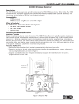
Mount the Receiver
Caution: Remove all AC and battery power from the panel before
installing or connecting any modules, cards, or wires.
1. Squeeze both sides of the device to gently separate the cover from
the base.
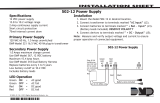
2. Secure the receiver to the wall in the desired location installing the
supplied screws in the mounting hole locations as shown in Figure 2.
3. Snap the cover back on the unit. The panel immediately recognizes
the 1100D Receiver if the panel is programmed with a house code.
RYGB
TO PANEL
Connects to Panel
Mounting Holes
Squeeze to
Remove Cover
Squeeze to
Remove Cover
Figure 2: 1100D Series Mounting Holes

LT-1289 20171 © 2020 Digital Monitoring Products, Inc.
7. TRANSMITTER SURVEY LED OPERATION
1100 Series transmitters provide a survey operation that allows one
person to confirm that each transmitter is communicating with the
wireless receiver or panel to easily determine the best location for the
transmitters and the wireless receiver. Follow the directions below to test
communication of the wireless transmitters:
1. Remove the transmitter’s cover.
2. Hold the transmitter in the desired location.
3. Press the tamper switch to send data to the wireless receiver and
determine if communication is confirmed or faulty.
Confirmed: If communication is confirmed, the survey LED turns
on when data is sent to the wireless receiver and o when
acknowledgment is received.
Faulty: If communication is faulty, the LED remains on for several
seconds or flashes multiple times in quick succession. Relocate
the transmitter or the wireless receiver until the LED confirms
clear communication. Proper communication between the
transmitter and wireless receiver is verified when for each press
or release of the tamper switch, the transmitter’s LED blinks
immediately on and immediately o.
8. IF 1100R REPEATER IS NEEDED:
Select a Location
Mount the 1100R on a flat surface. The 1100R Wireless Repeater is
typically mounted between the 1100 Series Receiver and the 1100 Series
transmitter(s) that are out of range. Locate as far from the 1100 Receiver
as needed to provide the required system range. Install the repeater away
from large metal objects. Mounting the repeater on or near metal surfaces
impairs performance. If the repeater is powered from an auxiliary power
supply, mount the repeater away from the metal power supply enclosure.
If the repeater is powered from the optional Model 376L plug-in power
supply, locate the repeater near a wall outlet not controlled by a switch.
When selecting the proper mounting location of a repeater, refer to the
LED Survey Operation section to confirm communication with the 1100
Receiver.
Tamper Switches
The 1100R is equipped with a case tamper and a wall tamper. A two
position header is provided to disable the wall tamper. To disable the wall
tamper, place the jumper across the two pins of the header. If wall tamper is
required, place the jumper over just one pin for storage.
Mounting the Receiver
1. Insert a small screwdriver and lift, as discussed in Mount the Receiver,
to remove the cover.
2. Secure the receiver to the wall ensuring that the wall tamper switch
makes proper contact with the wall. Use the supplied screws in the
mounting hole locations as shown in Figure 2.
3. Snap the cover back on the unit after observing LED operation.
6. 1100D RECEIVER OPERATION
The 1100D receiver automatically sends the panel house code to wireless
transmitters when the unique transmitter serial number is programmed into
the panel. The house code identifies the panel, receiver, and transmitters to
each other. The receiver only listens for transmissions using the specified
house code and/or programmed transmitter serial number.
Note: When setting up a wireless system, it is recommended to
program zones and connect the receiver before installing batteries in
the transmitters.
When a receiver is installed, powered up, or the panel is reset, the
supervision time for transmitters is reset. If the receiver has been powered
down for more than one hour, wireless transmitters may take up to an
additional hour to send a supervision message unless tripped, tampered,
or powered up. This operation extends battery life for transmitters. A
missing message may display on the keypad until the transmitter sends a
supervision message.
When any wireless zone programming is changed in the panel, receiver
zone programming is updated when exiting panel programming. During the
update, all wireless zones display as normal for approximately one minute,
regardless of the actual state of the wireless device(s).
External DC Plug-in Power Supply
When using the optional Model
376L plug-in DC power supply, use
the following steps to connect the
power supply:
1. Connect the Black wire with
White stripe to the positive
terminal on the 1100R and the
Black wire to the negative
terminal. See Figure 4.
2. Mount the 1100R near a wall outlet.
In addition to powering the repeater, the DC plug-in power supply also
charges the back-up battery. The 376L plug-in DC power supply must be
located within 100 feet of the repeater using 22 AWG wire or 250 feet using
18 AWG wire.
Optional Powering from External 12 VDC Power Supply
The 1100R can be powered from a 12 VDC
power supply such as a DMP Model 505-12. In
addition to powering the repeater, the power
supply also charges the back-up battery
of the repeater. If the DC power source is
removed, the power failure is indicated as an
open condition on the repeater zone.
Use the following steps to connect the power
supply:
1. Using 22 AWG wire, connect the J3 DC
Power 2-position Terminal Block to the
J6 terminalon the 505-12 power supply
PCB. See Figure 5.
2. Observe positive and negative polarity
on all connections.
Primary Power Loss Indication
When the 1100R is used with the XT Series or XTL Series a zone trouble
indication for the repeater zone occurs within three minutes of a loss of
primary power.
When used with the XR150/XR550 Version 206 or higher, a power loss
indication is displayed at the keypad as -ACPWR for the repeater zone. This
occurs within three minutes but a zone trouble report to the Central Station
receiver is delayed for one hour.
Rechargeable Battery
The 1100R rechargeable battery is used to provide up to 24 hours of backup
battery power when AC power is not available. The battery is intended for
backup power only and not to operate the 1100R Repeater on a daily basis.
If the battery is low, or not plugged into the J4 battery connector, a low
battery condition is indicated for the repeater zone.
Keypad Bus Wiring
The 1100D Wireless Receiver easily interfaces with the XT30/XT50 Series
panels using the keypad bus.
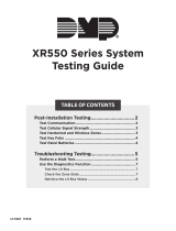
Harness Connection
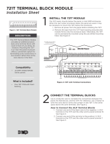
Refer to Figure 3, the panel programming guide and use the following steps
to connect the panel and receiver:
1. Using a 4-wire harness, connect from the 1100D Wireless Receiver
header (see Figure 3) to the panel keypad bus terminals 7, 8, 9, and
10. Observe wire colors when connecting to the terminals.
2. In System Options, program the House Code (1-50). In Zone
Information, program the wireless zones.
RYGB
TO PANEL
Black
Green
Yellow
Red
J4
RED PRO
J8
XT30/XT50 Series Panel
J7
RJ SUP
AC
1
2
3
4567
8
10
11 12
9
+B
BELL
GND
SMK
RED
YEL
GRN
BLKAC
-B
1100D
Receiver
Can be extended
up to 500 feet
from the panel
using 22 AWG
Figure 3: 1100D Series Wiring
Figure 5: 1100D Series
Mounting Holes
+ DC -
505-12 Power
Supply
12 VDC @
2 Amps
22 AWG Wire
DC Power
2-position
Terminal Block
- +
DC
Plug-in
Power
Supply
DC Power
2-position
Terminal Block
- +
- +
Black Wire
with White Stripe
to Positive
Black Wire
to Negative
Figure 4: DMP 376L Wiring

LT-1289 20171 © 2020 Digital Monitoring Products, Inc.
Conduct the Walk Test
Reset the control panel by momentarily placing a jumper on J16 then wait
one minute. From the keypad, enter the code 8144. The keypad displays
WALK TEST. If the system is monitored and the communication type is DD
or NET, the system sends a System Test Begin report to the central station.
All programmed zones are included in the test.
• STD (Standard Walk Test) - Select STD to Walk test zones. All
programmed zones are included in the test.
• WLS (Wireless Check-in Test) - Select WLS to automatically test
1100 Series wireless transmitter communications. Includes all
wireless devices except key fobs and transmitters programmed for a
supervision time of 0 (zero).
Note: For the XT30, Wireless Check-in Test operation only displays
when connected to 1100D Wireless Receiver Version 105 or higher.
• PIR (Wireless PIR Walk Test) - The PIR Walk Test allows the installer
to verify the 1126 operation. When enabled, the 1126 LED flashes each
time motion is detected for up to 30 minutes. This is a local test only
and no messages are sent to the Central Station.
Trip Counter for Walk Test (STD)
Displays the number of zone trips during the Walk Test.
• Each time a selected zone trips, the keypad buzzes and the bell
rings for two seconds.
• Each time a FI, FV, or SV zone trips, a Sensor Reset occurs.
END - Press the Select key directly below END to stop the Walk Test.
When the Walk Test ends or a 20 minute time-out expires, a final Sensor
Reset occurs. The System Test End message is sent to the receiver along
with Verify and Fail messages for each zone under test. Faulted zones
then display on the keypad.
Trip Counter For DMP Wireless Check-in Test (WLS)
Displays the number of wireless zones that automatically communicate a
supervisory check-in message.
• The number of zones that check in. (XX in the example).
• The total number of wireless zones programmed for supervision
that should check in. (ZZ in the example).
END - Select END to stop the Wireless Check-in Test. When the test
ends or a 20-minute time-out expires, normal wireless zone processing
returns. If all transmitters check-in, both numbers will match within three
minutes. If a transmitter has multiple zones (1101, 1114, etc.), all zones will
be included in the counts. Failed wireless zones will then display on the
keypad.
9. COMPLETE INSTALLATION
After system power-up, perform the following steps to set the panel up for
remote programming.
1. Reset the panel using the reset jumper. Remove the jumper and store
it on one J16 pin for future use.
2. At the 7060 Keypad set to Address #1, enter 6653 and press CMD.
3. At the INITIALIZATION menu press any top row Select key.
4. Answer YES to all Initialization options.
5. Panel is now ready to be programmed. See panel programming
guide.
6. Press CMD until STOP displays.
Note: The information entered is NOT SAVED until you run the STOP
routine.
7. At the STOP menu press any top row Select key to save the
programming.
8. The system is now ready to program using Remote Link™
10. CONNECT THE TRANSFORMER AND AC POWER
Do not plug power cord into dedicated outlet not controlled by a switch
until all devides are connected to the panel.
Note: Never share the transformer output with any other equipment
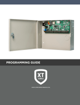
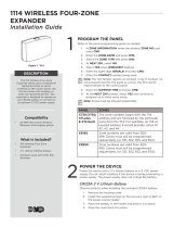
11. ZONE LAYOUT
Zones 1-10 are located directly on the XT30/XT50 Control Panel. Zones 1
through 9 each terminate with 1k Ohm EOL resistors. Zone 10 terminates
with 3.3k Ohm EOL resistors.
12. WIRING
See Figures 6 and 7 that illustrate the XT30/XT50 wireless wiring details.
13. WALK TEST
About the Walk Test
The XT30/XT50 panel provides a walk test feature that allows a single
technician to test all the protection devices connected to zones on the
system. Conduct the Walk Test within 30 minutes of resetting the panel.
The Walk Test automatically ends if no zones are tripped for 20 minutes.
TEST IN PROGRESS displays at all keypads. When five minutes remain,
TEST END WARNING displays. If any areas are armed the Walk Test does
not start and SYSTEM ARMED displays.
Test End Warning
When no zones have been tripped and five minutes remain on the 20
minute Walk Test timer, the keypad displays TEST END WARNING and
the keypad tones. If no additional test zone trips occur, the test ends and
a final Sensor Reset automatically occurs. The System Test End message
is sent to the receiver along with Verify and Fail messages for each zone
under WALK test. Faulted zones then display on the keypad.
Failed Zones Display
Each zone that did not trip at least once during the Walk Test displays
on the keypad that initiated the test. Any Fire (FI) Panic (PN) or
Supervisory (SV) 24-hour zone that is faulted at the end of the Walk
Test displays a trouble condition for that zone regardless of the message
programmed for the open or short condition of the zone and a zone
trouble is sent to the receiver. Press the CMD key to display the next
failed zone.
For the Wireless Check-in Test, failed wireless zones display only on
the keypad. Zone Verify/Fail reports are not sent to the central station
receiver for the wireless checkin test.

4 Digital Monitoring Products [Customer/Title] Quick Start Guide ([KIT Ordering Number])
RYGB
TO PANEL
J3
Phone Line
Outputs
J11
1
2
3
4
J1
Ethernet
J16
Reset
J20
Wireless
Antenna
connection
J7 RJ
Supervision
J24 Cellular
header
J18
Load
RED
Programming
J8
Cold Water Pipe
Earth Ground
Bell Sup.
1k Ohm
EOL
Resistor
Zones 1-9 1k Ohm EOL Resistor
To DMP 321
Transformer
Battery Positive
Battery Negative
Zones 10 3.3k Ohm
EOL Resistor
1100D Receiver
To DMP 321
Transformer
J3
Phone Line
Outputs
J11
1
2
3
4
J1
Ethernet
J16
Reset
J20
Wireless
Antenna
connection
J7 RJ
Supervision
J24 Cellular
header
J18
Load
RED
Programming
J8
Cold Water Pipe
Earth Ground
Bell Sup.
1k Ohm
EOL
Resistor
Zones 1-9 1k Ohm EOL Resistor
To DMP 321
Transformer
Battery Positive
Battery Negative
Zones 10 3.3k Ohm EOL Resist
or
XT50
only
To DMP 321
Transformer
Figure 6: XT30 Application
Figure 7: XT50 Application
/