1119 Wireless Door Sounder
Description
The Model 1119 Wireless Door Sounder is a single-zone transmitter equipped with a battery powered sounder.
The 1119 provides a cover tamper, a sounder cutoff selection of one second or ve minutes, survey LED, and two
batteries. The 1119 zone input can be connected to a standard door contact, typically attached to an emergency
exit door for local annunciation during the day and burglary alarm annunciation at night. The sounder always
automatically turns on when the door opens. The 1119 sounder is silenced after one second or ve minutes or can be
silenced remotely from the panel at disarm or from the user menu.
Compatibility
• All DMP 1100 Series Wireless Receivers and Burglary Panels
What is included
The 1119 includes the following:
• One 1119 with zone input and wireless sounder
• Two 3.0V Lithium CR123A batteries
• Hardware pack with 470k EOL Resistor
• Serial number labels
Serial Number
For your convenience, two additional pre-printed serial number labels are
included for the zone and sounder output. Prior to installing the wireless
sounder, record the serial numbers or place the pre-printed serial number
labels on the panel programming sheet. One serial number is for the input
zone and the other is for the output. These numbers are required during
programming.
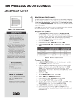
Sounder Cutoff Jumper
The 1119 provides a sounder cutoff jumper (J5) that causes the 1119 to automatically turn off the
sounder after one second or ve minutes depending on the jumper position.
When the onboard 1119 zone is tripped, the 1119 turns on the sounder output for one second if the
jumper is placed on the two left pins or for ve minutes if the jumper is placed on the two right
pins.
When the sounder output is programmed in Output Information and is turned on by an output
command from the panel such as a different zone trip, group output, or manually from a keypad, the 1119 always
turns the sounder output off automatically after ve minutes regardless of the position of the jumper (J5).
In addition, when the sounder output was turned on by a panel output command and then automatically turned off
by the 1119 after ve minutes, the sounder output cannot be turned back on by the panel until the 1119 receives a
panel output off command as described below.
Silencing the Sounder
The following panel operations can silence (turn off) the sounder:
• Bell Output (XR100/XR500)
Program the output in Bell Output so the output turns off at the Bell Cutoff time if less than ve minutes.
• Disarming (All panels)
Program the output in the Alarm Action output section of the zone that will be disarmed and set the action
to Steady
• Outputs On/Off (All panels)
From the User Menu, choose Outputs On/Off, enter the output number and choose Off
• Output follows 1119 zone condition (All panels)
Program the output in the Alarm Action output section of the 1119 zone programmed in Zone Information
and set the action to Follow. When the 1119 zone restores, the output is turned off.
See Programming the 1119 in the Panel section for additional information.
Zone Bypassed
When the 1119 sounder output (programmed in Output Information) and in the Alarm Action output section of Zone
Information becomes bypassed in the panel, subsequent tripping of the 1119 zone turns on the sounder but because
the 1119 panel zone is bypassed, the panel turns off the sounder output within a few seconds.
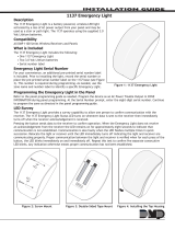
Figure 1: 1119 Wireless Sounder
SOUNDER
CUTOFF
1
SEC
5
MIN
InstallatIon GuIde

Digital Monitoring Products 1119 Installation Guide
2
Programming the 1119 in the Panel
To allow the 1119 sounder to be turned on or silenced by the panel, the OUTPUT serial number must be programmed
as an output in Output Information, and assigned to the 1119 zone ALARM ACTION output section in panel Zone
Information programming.
If the 1119 is programmed as a zone, but the output is not programmed into the panel at Output Information, the
1119 annunciates up to ve minutes dependant on the sounder cutoff jumper setting and cannot be silenced from
the panel.
If the 1119 is programmed into Output Information, but not assigned to the 1119 zone ALARM ACTION output section,
the sounder only operates for a few seconds when the 1119 zone is tripped even if the sounder cut off jumper is set
to ve.
Output Programming
Enter the output number, output name, and eight digit OUTPUT serial number. For extended battery life, a 15
second slow response output is recommended. This gives the 1119 an estimated battery life of 2 1/2 years,
depending on usage. A list of the slow response outputs for each panel is listed below.
XR100/XR500: 450-474 XTL/XT30/XT50: 31-34
Use the following output numbers for fast response outputs that respond within 1 second. The typical battery life is
3 months. Fast response outputs are listed below.
XR100/XR500: 480-499 XTL/XT30/XT50: 41-44
Zone Programming
Program the 1119 in Zone Information as a Day type zone (DY) when local annunciation at the keypad is required in
addition to the sounder when the panel is disarmed. If the 1119 sounder is to be the only annunciation during the
disarmed state, program as a Night type zone (NT). At the Serial Number: prompt enter the eight-digit ZONE serial
number. To allow the panel to control the output, program the output number in the zone ALARM ACTION.
Supervision Time
When programming the 1119 in both Zone Information and Output Information, the supervision time should be the
same, typically 240 minutes for burglary applications.
Note: When a receiver is installed, powered down and powered up, the panel is reset, or programming is complete,
the supervision time is reset. If the receiver has been powered down for more than one hour, the 1119 may take
up to an additional hour to send a supervision message unless tripped, tampered, or powered up. This operation
extends battery life. A missing message may display on the keypad until the supervision message is sent. Refer to the
panel programming guide as needed.
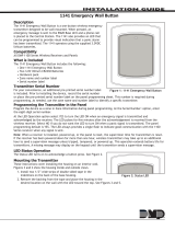
Selecting the Proper Location (LED Survey Operation)
The 1119 provides a survey capability to allow one
person to conrm communication with the receiver
while the cover is removed. The 1119 PCB Red Survey
LED (See Figure 2) turns on whenever data is sent to
the receiver then immediately turns off when the
receiver acknowledgement is received. Pressing the
tamper switch is a convenient way to send data to the
receiver to conrm operation. When the 1119 does
not receive an acknowledgement from the receiver
the survey LED remains on for about 8 seconds to
let you know communication is not established.
Communication is also faulty when the LED ashes
multiple times in quick succession. Relocate the
1119 or receiver until the LED immediately turns off
indicating the 1119 and receiver are communicating
properly. Proper communication between the 1119 and
receiver is veried when for each press or release of
the tamper switch, the LED blinks immediately on and
immediately off.
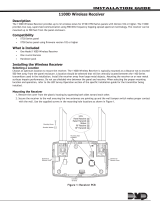
Figure 2: 1119 Wireless Sounder PCB
Mounting Holes
Model
1119
RED LED
(SURVEY)
TAMPER
SWITCH
SOUNDER
Mounting Holes
Zone
terminals
Red
Survey
LED
Locking Screw
Locking Screw
1
SEC
5
MIN
SOUNDER
CUTOFF
ZONE
OUT

1119 Installation Guide Digital Monitoring Products
3
Installing the 1119
Mount the 1119 on a at wall or single-gang box away from large metal objects. See Figure 2 for mounting hole
locations.
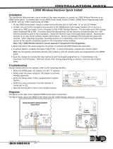
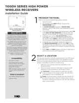
1119 Zone Wiring
It is recommended to locate zone devices such as a door contact within 100 feet of the
1119 sounder. Use 22 or 18 AWG wire to complete the connections between the 1119
zone and the zone device. Terminate the zone with the included 470k EOL resistor as
shown.
The 1119 has been designed primarily for use with the XR100 and XR500 Series control
panels and is capable of sending to the wireless receiver the open, normal, or short
condition of the zone. In addition, a separate tamper signal is sent. However, when used
with the XTL or XT30/XT50 Series panels, the tamper indication is sent to the panel as
an open condition of the zone. When programmed as a Day type zone, an 1119 tamper
during the day is annunciated at the keypad as an Alert. When programmed as a Night type zone, a tamper during
the day is annunciated as a Tamper at the keypad.
Powering the 1119
Note: When setting up a wireless system, it is recommended to program the zone and sounder output, and
connect the receiver before installing batteries in the 1119.
Battery Power
Observe polarity when installing the batteries. Use only 3.0V Lithium batteries, DMP Model CR123, or the equivalent
battery from a local retail outlet.
1. Remove the locking screw from the sounder housing. See Figure 2.
2. Lift the cover from the bottom to remove.
3. If replacing the batteries, remove the used batteries and dispose of properly. Always replace both batteries
at the same time.
Caution: Properly dispose of used batteries. Do not recharge, disassemble, heat above 212°F (100°C), or
incinerate. There is a risk of re, explosion, and burns with improper disposal.
4. Place the two 3.0V Lithium batteries in the holders and press into place. See Figure 2 for battery location.
5. Set the cover back in place and replace the locking screw.
Battery Life Expectancy
Typical battery life expectancy for the 1119 is 2 1/2 years when programmed as a slow response output where the
sounder is operated for ve minutes once a month and 3 months when programmed as fast response output. Refer
to the XR500 Series Programming Guide (LT-0679), the XR100 Series Programming Guide (LT-0896), the XT Series
Programming Guide (LT-0981) or the XTL Programming Guide (LT-1108) as needed. DMP wireless equipment uses
two-way communication to extend battery life.
The following situation can extend battery life expectancy:
• Using a slow response output
• Infrequent transmission trips, such as a door that is rarely used
• Extend transmitter supervision time in panel programming
The following situations can reduce battery life expectancy:
• Multiple sounder on/off operations
• If a receiver is unplugged or not installed
Note: Transmitters continue to send supervision messages until a receiver returns an acknowledgement.
After an hour the transmitter only attempts a supervision message every 60 minutes.
• Using a fast response output
• When installed in extreme hot or cold environments
470k EOL
Figure 3: Zone Terminal

LT-1063 © 2013 Digital Monitoring Products, Inc.
12025
800-641-4282
www.dmp.com 2500 North Partnership Boulevard
Compatibility
The 1119 Wireless Door Sounder is compatible with:
XR100/XR500
• 1100X Wireless Receiver Version 104 or higher
• 1100XH Wireless Receiver Version 105 or higher
XT30/XT50
• 1100D Wireless Receiver Version 104 or higher
• 1100DI/1100DH Wireless Receivers Version 105 or
higher
Built-in 1100 Series Recevier
• XT50 Series panels Version 101 or higher
• XTL panels
Patents
U. S. Patent No. 7,239,236
Listings and Approvals
FCC Part 15 Registration ID CCKPC0123
IC Registration ID 5251A-PC0123
FCC Information
This device complies with Part 15 of the FCC Rules. Operation is subject to the following two conditions:
(1) This device may not cause harmful interference, and
(2) this device must accept any interference received, including interference that may cause undesired operation.
The antenna used for this transmitter must be installed to provide a separation distance of at least 20 cm (7.874 in.)
from all persons. It must not be located or operated in conjunction with any other antenna or transmitter.
Changes or modications made by the user and not expressly approved by the party responsible for compliance
could void the user’s authority to operate the equipment.
NOTE: This equipment has been tested and found to comply with the limits for a Class B digital device, pursuant
to part 15 of the FCC Rules. These limits are designed to provide reasonable protection against harmful
interference in a residential installation. This equipment generates, uses and can radiate radio frequency
energy and, if not installed and used in accordance with the instructions, may cause harmful interference
to radio communications. However, there is no guarantee that interference will not occur in a particular
installation. If this equipment does cause harmful interference to radio or television reception, which can be
determined by turning the equipment off and on, the user is encouraged to try to correct the interference
by one or more of the following measures:
- Reorient or relocate the receiving antenna.
- Increase the separation between the equipment and receiver.
- Connect the equipment into an outlet on a circuit different from that to which the receiver is connected.
- Consult the dealer or an experienced radio/TV technician for help.
Specications
Battery
Life Expectancy 2 ½ Years (Slow Response)
3 Months (Fast Response)
Type 3.0V Lithium CR123A
See Battery Life Expectancy for full details.
Frequency Range 903-927 MHz
Dimensions 4.65” L x 3.1” W x 1.4” H
Color White
Housing Material Flame retardant ABS
Accessories
CR123 DMP 3.0V Lithium Battery
/