Page is loading ...

Qty
Ebay Parts List
P/N Description
15405 1.9” Ebay Laser Cut Sheet Thin 1
15406 1.9” Ebay Laser Cut Sheet Thick 1
30935 1.9” Ebay Instructions 1
09184 Simple Switch with 4” Wires 1
13066 Weld Nut for Rail Button 2
12980 6-32x3/8 Thumb Screw 2
12981 4-40x5/16 Nylon Fillister Slot Machine Screws 4
13075 Removable Plastic Rivet 3
30326 Kevlar Shock Cord 300# in Feet 6 ft
47122 Clear Plastic Bag 6x14 1
www.ApogeeRockets.com
Colorado Springs, CO
Made in the USA
0 56779 10545 3
Booklet P/N 30935
1.9”
Fits Aerotech 1.9” diameter rockets.
Uses coupler and payload tube included
with select Aerotech Kits.
KIT #10545

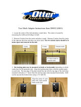
Detailed Parts Sheet/Checklist
Tools Needed
Parts Included
Parts Not Included
“I” Part (2 metal thumb screws)
“F” Part (Tube Coupler)
*Included in Aerotech Kit*
“G” Part (3 black rivet sets)
“M” Part (Body Tube)
*Included in Aerotech Kit*
“H” Part (2 metal weld nuts)
S
wit
ch
“A-D” Parts (1 thin plywood sheet)
P/N 15405
P/N 02090
P/N 13003
P/N 13075 P/N 13066
P/N 12980 P/N 12981
P/N 09201
P/N 03078
P/N 09210
or 09204
P/N 09104
P/N 09184
P/N 30326
P/N 10142
“E” Part (1 thick plywood sheet)
P/N 15406
Altus Metrum EasyMini PerfectFlite StratoLoggerCF
“N” Parts (compatible altimeter options)
“P” Parts (2 igniters)
*We recommend the Quest Q2G2
Igniters
“O” Part (Li-Po battery)
“K” Part (electronic switch)
“J” Parts (4 small plastic screws)
“L” Part (6ft of Kevlar shock cord)
Wood Glue
Thick Super Glue
Small Screwdriver Set
Sand Paper
Tape
4-40 Tap and Drill Set
*available for purchase from Apogee
Latex Glove
TYPE FFFF
Black Powder
*Available at a
gun store
Marker
7” of String
Hand Drill
* You also need a 5/32” Drill bit and a
1/4” Drill Bit
5/32” Holes
1/4” Hole
Align with edge of payload tube
Paper Wrap Marking Guide

Apogee 1.9” Ebay Assembly Instructions
Aligning
marks
Tube coupler
sticking out
Tape
Make sure the marking guide
is aligned with end of tube
Tube coupler
Step 2 Step 3
“C” Shape
“D” Shapes
B2
A2
A1
B1
“A2” Shape (larger disk)
“A1” Shape (smaller disk)
“B2” Shape (larger disk)
“B1” Shape (smaller disk)
“E” Shape
“E1” side
“E2” side
E1
E2
S
w
i
t
ch
Step 4
Top Side of Sled
Sand
surfaces
rst
Side View
Wider side on top
Wood glue
goes here
Step 7
Side View
Side View
Step 8
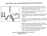
1. Mark your tube coupler in the middle with
a pen or pencil. Insert the coupler into the main
parachute bay tube up to the line and tape it to
hold it into place.
2. Cut out the “Paper Wrap Marking Guide”
from the “Detailed Parts Sheet/Checklist” page
of this instruction manual. Wrap the guide
around the back end of the main parachute bay
tube and tape it into place.
3. Carefully drill holes through both tubes
using the marked areas on the guide.
*Once you’re nished and you’ve removed the
guide, cleanly sand the cardboard fuzz away
from the holes. Apply a small amount of thin
super glue to the recently drilled holes. Allow
the glue to dry and then gently sand off any
excess glue. This will help clean up the edges
and strengthen the holes you made.
4. Mark the wood parts with a pencil (ex-
cept the sled “E” for now) using the example
image to the right. *They are already etched
on the plywood sheet but marking the shapes
themselves with a pencil will serve as a helpful
reference during the assembly process.
5. Remove the sled Shape “E”, the 2 disks
“B1 & B2” and Shape “C” from their plywood
sheets. Leave the other pieces in for now. Re-
move the small excess pieces inside the slots &
holes with a pencil or screwdriver.
6. Gently sand both sides of the sled and
test t one of the “B” disks on each end. The
disk should slide on and off easily on both ends
when completed. Now mark the ends of the
sled with a pencil as “E1 & E2”. Use the image
example in Step 4.
7. Sand the sides of Shape “C” and then
place it into the slot on the sled. Make sure
the wider end sticks up from the side of the
sled that shows the Apogee logo imprint. Once
securely in place, dab a small amount of wood
glue on the joining pieces along the non-
Apogee side and let dry.
8. Insert Metal Weld Nuts “H” into Shape
“C” with male ends facing outwards towards
Apogee logo imprint. Apply thick super glue to
the weld nuts to secure them into place. *Be
careful not to get super glue in the threads.
Also, you can center the weld nuts by placing
the A1 piece on the end while gluing the them
into place.
Rocket Tube Preparation/Sled
Assembly
Page 3
The end of this tube
Step 1

Press both disks
onto the edge of the
sled and remove
after they are
together
Step 10
Apply the wood
glue here before
pressing the disk
together
Step 9
Step 11
Marker line
Step 12
9. Place the smaller of the disks, “B1” on
the “E2” end of the sled and slide it up until it
stops. Now apply a small amount of wood glue
to the outside surface of the “B1” disk. Then
take your larger disk “B2” and quickly slide it
up against “B1” (Use the image on the right for
reference). Immediately wipe off any glue that
oozes out of the pieces on the outside of the
disks. Now apply a llet of wood glue to where
the sled meets the disks and let dry.
10. For the opposite side of the sled: Re-
move the disk shapes “A1 & A2” from the
wood kit and remove the excess pieces inside
them with a screwdriver or pencil. Place the
smaller disk “A1” on the “E1” side of the sled
rst. Then place the larger disk “A2” on after it.
Dab a small amount of wood glue between the
2 disk and then press them together. DO NOT
GLUE THESE DISKS TO THE SLED. Once
they begin to dry make sure to pull the disks
off the end of the sled and set aside for now.
*Wipe off any excess glue that oozes out along
the outside edges.
11. Temporarily insert the assembled sled
into the Tube Coupler Part “F” (Included in
the Aerotech Kit) and rotate the coupler to
align your switch hole with the sled. Then, mark
the side/edge of the sled through the hole.
12. Remove the sled from the coupler. Align
the switch button with the mark you made in
the prior step and thick super glue it to the sled
using thick super glue.
*Be very careful not to glue the switch
button itself or the inside of the switch. This
may permanently damage the switch and
prevent it from working properly.
*You may need shorten the wire lengths by
cutting and re-stripping the ends.
13. Take your Altimeter “N” and align it with
the corresponding holes on the Sled “E”. The
PerfectFlite StratoLogger CF altimeter will align
with the holes spaced farther apart and the
Altus Metrum EasyMini altimeter with the holes
that are closer together.
Sled Assembly Continued...
Page 4
PerfectFlite StratoLoggerCF
Altus Metrum EasyMini
Step 13

14. Once your corresponding holes are
determined, carefully remove the laser cut holes
on the sled with a small screwdriver or pencil.
Feel free to rub a small amount of wood glue
into the remaining holes that won’t be used to
seal them.
15. Use your 4-40 tap and drill kit to hand
thread the open holes for your altimeter place-
ment.
16. Flip the sled over and tape the Li-Po
battery to the bottom of the sled. *When setting
the tape in place, try to avoid the holes that you
need for the altimeter placement.
17. Remove 4 of the wooden washers Part
“D” from the plywood sheet. The remainder can
be saved and used later if needed. They are
provided as extras. *Refer to the “Step 4 Image”
on Page 3 for help locating these.
18. Flip the sled back over to the top side,
and carefully place the 4 small wooden wash-
ers over the corresponding holes. Then slowly
place the altimeter on top of your wooden
washers.
19. Use your screwdriver to insert the small
plastic screws Part “J” into the corner holes on
the top of the altimeter and into the threaded
holes in the sled assembly. You may need to
carefully adjust the washer placement as they
can slide around while you insert the screws.
NOTE: The screws will not extend from the
bottom side of the sled
20. Attach the switch wiring to the altimeter
(per your altimeter instructions).
21. Connect the battery to the altimeter (refer
to altimeter instructions for details).
Sled Assembly Continued...
Step 14
Step 15
Page 5
Side View
Altimeter
Wooden Washers
Top View
Step 18
Switch Connection
Screw Placement
Steps 19-20
Tape Battery
E2 Side
Bottom of Sled
Step 16

22. Trim the exposed wires on the igniters to
1/8th inch. This will prevent any shorts from the
exposed wires touching each other. Then attach
the Drogue and Main igniters to the terminal
block on the altimeter.
*Refer to your specic altimeter instructions
for further details and MAKE SURE YOUR
ALTIMETER IS CONFIGURED TO YOUR
PREFERENCES AT THIS POINT, BECAUSE
IT WILL BE HARDER TO ACCESS AFTER
YOU COMPLETE THE EJECTION CANISTER
SETUP.
23. Now feed the Main igniter through the
hole in the disk on the “E2” side of the sled.
Then bend the Drogue/Apogee igniter around
the left side of the “C” shape and towards the
“E1” side of the sled.
24. Slide the coupler tube over the sled
assembly. (Use the diagram on the right for ref-
erence). The tube will slide over the “B1” part
of the disk and butt up against “B2”.
25. Take your completed disk piece from
Step 10 “A1& A2” and place it over the open
end of the sled. Make sure the smaller side of
the disk piece goes on rst and insert the igniter
through the smaller hole.
26. Screw both Metal Thumb Screws Part
“I” into the open holes on the “E1” part of the
sled. Tighten the screws to secure the t.
You may need to rotate the tube around while
tightening it in order to align the switch with the
open hole on the tube.
Igniter Assembly
Page 6
Terminal block
Drogue/Apogee Igniter
goes around the “C” shape towards “E1” Side
(bottom of the rocket)
Hole for “Main” Igniter
C Shape
Main Igniter goes towards the “E2” Side of the sled
and through the small hole on the end.
Steps 22-23
B2 Shape
B1 Shape
Step 24
Main
Igniter Side
Apogee/Drogue
Igniter Side
Step 25
Make sure the switch is visible from the tube hole
Step 26

Page 7
*VERY IMPORTANT* MAKE SURE THE SWITCH IS IN THE
“EXTENDED/OFF POSITION” BECAUSE YOU WILL NOW BE
CONNECTING BLACK POWDER TO THE IGNITERS.
27. Take your latex glove and measure it at
about 1.25” from the end of the nger tips, then
cut 2 of the ngertips off.
28. Measure and cut a piece of string at
about 7” long. Cut it again in half. This will give
you two 3.5” pieces of string, one for each side.
29. Fill the inside of each cut nger tip from
the glove with 0.5 grams of black powder. *Your
rocket may need more or less black powder.
Consult your ejection charge calculator.
30. Set the Ebay down on a at surface
and then place the Apogee/Drogue igniter
through the open end of the nger tip. Attempt
to squeeze most the air out of the bottom of the
ngertip.
31. Wrap the string around the cut nger tip
of the glove. Then tie a knot just above the
top of the black powder line being sure to
leave no air pockets above the powder.
32. For the Main igniter setup, repeat steps
30 & 31 above.
33. Tie the shock cord from the main body
tube of the rocket to the “E1/Apogee” side of the
sled. Use a knot that you can untie easily after
launch.
34. Tie your Kevlar cord to the “E2” end of
the Ebay sled. Now place the Ebay into your
upper parachute rocket tube (with the “E2” side
facing upwards towards the nose cone). Make
sure to align the switch hole and rivet holes.
The Kevlar cord passes through the tube and
ties to the nose cone.
35. Place the bottom end of your rivet into
the hole through your rocket and press it in.
Then place the top end of the rivet all the way
into the bottom piece. This will lock the Ebay
into place. Repeat this process for the remain-
ing two rivets. *To remove the rivet simply grab
the top piece and pull.
36. Take the main parachute bay tube and
slide your completed Ebay into the end.
37. Congratulations, the Ebay assembly
is complete and ready to be placed into your
rocket!
Make Ejection Canisters
Step 29
1.25”
glove ngertips
string
cut in half at 3.5”
Steps 27-28
For this
step rest
Ebay
on at
surface
Igniter
Igniter
For this
step rest
Ebay
on at
surface
Step 30
Igniter
Igniter
String
For this
step rest
Ebay
on at
surface
For this
step rest
Ebay
on at
surface
Step 31
E2
E1
Step 33 Step 34
Switch Hole
Inside the tube
Step 35

Go online and order at the website above or call us and order at
719-535-9335. We’re available M-F: 9:00am-5:00pm MST.
www.ApogeeRockets.com
✓
Recommended items: Product Number
4-40 Tap and Drill Set 02090
Altimeter Options:
Easy Mini
PerfectFlite StratoLogger CF
09201
09104
2 Quest Q2G2 Long Motor Starters 03079
Battery Options:
400mAh LiPo Battery
900mAh LiPo Battery
09210
09204
JST LiPo Battery Connector with Wires
(For StratoLogger CF Connection to LiPo Battery)
09301
For video tips/instructions on how to set-up your dual-deployment rocket go to our website link at
https://www.apogeerockets.com/Advanced_Construction_Videos/Rocketry_Video_26
/