Page is loading ...

Page 1
Other Tools and Materials Needed
• Scissors
• Hobby Knife
• Pencil
• Wood Glue (or White Glue)
• FIXIT
®
Epoxy-Clay (www.ApogeeRockets.com/epoxy-clay.asp)
• Masking Tape
• Sandpaper & Sanding Block
• Ruler
• Sanding Sealer
• Paint Brush
• Spray Paint
Aspire Parts List
P/N Description Qty
10091 Airframe Tube (AT-24/3.75”) 1
10110 Airframe Tube (AT-29/13”) 2
13008 Airframe Coupler (AC-29) 1
13031 Centering Ring (CR18-24) 1
13035 Centering Ring (CR24-29) 4
13056 Launch lug (SBL-0328) 3” Long 1
19114 Plastic Nose Cone (PNC-29A) 1
15531 Balsa Fin Sheet 1
30305 Mylar Streamer 4” X 56 ” 1
29326 300# Kevlar Shock Cord (36” Long) 1
37012 Tube Marking Guide Sheet 1
41020 Decal Sheet 1
31048 Aspire Instruction Sheet A 1
31049 Aspire Instruction Sheet B 1
Kit # 5024
Another quality ying model rocket kit from:
Apogee Components, Inc.
3355 Fillmore Ridge Heights
Colorado Springs, CO 80907 USA
Visit our web site at: www.ApogeeRockets.com
Skill Level 2 - Previous Experience Suggested
The Apogee Aspire kit was designed with one purpose in
mind. To achieve the highest possible altitudes from 29mm
composite propellant motors. On the Apogee Components’
F10 motor, this rocket is capable of ying higher than 1 mile! It
can go even higher on 29mm G and H motors.
This is an easy to build kit, and can be further reinforced to
y with high thrust motors. By doing so, it is also capable of
speeds exceeding Mach 1 on a G80 rocket motor. WOW!
While the model is easy and straight-forward to build, I recom-
mend that you read the entire set of instructions rst. By doing
this, you’ll be able to construct this model in a very fast and
efcient manner.
Sheet A - P/N 31048

Page 2
Apogee Aspire Rocket Assembly
1. Fine sand the balsa die-cut sheets before
removing the ns. Carefully remove all the
pieces from the balsa sheet by freeing the edges
with a sharp hobby knife.
2. Group the four ns together, and gently
sand the edges as shown in the illustration.
3. Test t the red coupler in place into one
of the body tube sections (If you have trouble
inserting it, try sanding the coupler or peeling off
some of the red paper layer). Apply wood glue
around the perimeter to one end of the red tube
coupler. Quickly insert it 1/2 way into one end of
a 29mm diameter body tube. After the glue has
set, apply glue around the portion sticking out,
and insert into the other 29mm body tube.
Note: If you plan on using longer 29mm rocket
motors than the 3.5” (8.9 cm) long Apogee F10
composite propellant motor, you may omit the
next step.
4. Carefully glue one of the CR24-29 center-
ing rings into one end of the body tube assembly
using wood glue. Recess it 3-1/8 inch (7.9 cm)
into the tube from the end. It is easiest to push it
into the tube using a 29mm diameter rocket mo-
tor. From now on, this end of the tube will be the
aft end of the tube.
5. Cut out the tube marking guide from the
pattern sheet. Wrap the guide around the aft end
of the body tube and tape the ends together.
Mark the body tube at each of the arrow points.
Remove the marking guide.
6. Using a door frame, draw a pencil line
down the outside of the body tube at each pencil
mark. Label the launch lug line so you don’t glue
a n in the wrong position.
7. Apply glue to the root edge of one of
the ns. Allow the glue to dry slightly for a few
minutes, then attach it to one of the body tubes,
as shown in the illustration. Each n is attached
.75” (19mm) from the end of the tube. Make sure
the n is straight along the tube. Allow the n to
dry before proceeding with the next n. Repeat
this step three more times as you attach the
other two ns.
8. Apply a bead of wood glue to both sides of
each n-body tube joint. Pull your nger along
the joint to smooth out and remove the excess
glue. Lay the tubes horizontally while the glue
dries. (Note: If you plan on ying with high thrust
rocket motors to achieve supersonic speeds, it
is recommended that you apply a llet of FIXIT
®
Epoxy-clay (www.ApogeeRockets.com/epoxy-clay.
asp) to each of the ns to add extra strength.
.75” (19mm)
Mark Motor Casing
3-1/8” (7.9 cm)

Page 3
9. Using wood glue, attach the launch lug to
the tube. Position it on the pencil line, about 4
inches (10.2 cm) from the end of the tube near-
est the ns. Allow the glue to dry. (Note: If you
plan on ying with high thrust rocket motors to
achieve supersonic speeds, it is recommended
that you apply a llet of FIXIT
®
Epoxy-clay to
each side of the launch lug for extra strength.
10. Tie one end of the Kevlar
®
shock cord to
the loop on the base of the nose cone. Tape the
streamer to the shock cord, near the nose cone.
Make sure the streamer is securely attached so
that it can’t come off.
11. Cut the paper shock cord mount anchor
from the pattern sheet. Spread wood glue over
one side of the paper and position the free end
of the shock cord at a slight diagonal across the
length of the paper. Fold the paper twice at the
fold lines indicated on the pattern. Squeeze it
between your ngers, and at the same time, curl
the edges slightly to match the inside curvature
of the body tube. When the glue has set, glue
the assembly inside the body tube. Be sure to
position it far enough into the tube so that the
nose cone can fully be inserted into the tube.
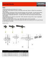
Construction of 24 mm Motor Adapter
12. Glue one large centering ring (CR24-29)
on the forward end of the 24 mm diameter tube.
It should be ush with the end of the tube.
13. Glue the remaining two centering rings
(CR24-29) on the other end of the tube, 3/8 inch
(9.5 mm) from the end of the tube. Smear a thin
lm of wood glue on all the outside surfaces of
the centering rings to prevent the paper from
fraying.
14. Glue the smaller centering ring (CR18-24)
inside the 24 mm diameter tube as an engine
block. It is recessed 7/8 inch (22.2 mm) from the
forward end. Use a scrap piece of balsa to help
apply the glue to the inside of the tube. Again,
use a rocket motor to push the motor block into
the tube (see step #4).
4.0” (10.2 cm)
FIXIT
®
llet
Tie shock cord to base of nose cone.
Tape streamer to shock cord.
2.0” (5 cm) minimum
7/8” (22.2mm)
3/8” (9.5 mm)
Section A-A
A
A

Page 4
Finishing the Rocket
15. After all the glue has completely dried,
you may now paint your Apogee Aspire model
rocket. Sealing and sanding the balsa parts re-
duces drag (higher ights) and greatly improves
the rocket’s appearance. Apply a coat of sanding
sealer to the ns with a paint brush. When the
sealer is dry, lightly sand the sealed surfaces.
Repeat the sealing and sanding procedure until
the balsa grain is lled and the ns look and feel
smooth.
16. Roll a piece of paper and insert it into
the aft end of the body tube so you can hold the
model while painting it. For best results, paint
the model with primer before using the nal paint
colors. Follow the directions on the paint can,
and always paint outdoors with the wind against
your back. Let the paint harden at least 24 hours
before proceeding. You may mask and paint the
model to match the picture on the cover.
17. Cut around the perimeter of the decal
with a pair of scissors. Peel off the paper back-
ing, and afx the decal in place on the model.
Use the picture on page 1 for decal placement.
Inserting and Retaining a 29mm motor into the Apogee Aspire
Tape around
tube and
motor.
Inserting and Retaining a 24mm motor into the Apogee Aspire
using the 24mm motor mount adapter assembly.
Tape around
tube and motor
Tape around tube and
motor adapter
The largest motor size (29 mm dia.) is simply
taped into the aft end of the rocket. Wrap tape
around the outside of the motor and the aft end
of the body tube as shown.
The smaller motors (24 mm dia.) are rst taped
into the motor adapter. Then the adapter is in-
serted into the rocket – one of the CR24-29 rings
extends out of the tube. Tape is applied over the
rocket and the aft centering ring of the motor
adapter as shown in the illustration.
Installing rocket motors into the Apogee
Aspire Kit

Page 5
Launch Supplies Needed
To Launch your rocket you will need the
following supplies:
•
A model rocket launching system
•
Flame resistant recovery wadding
•
Recommended Rocket Engines: See the
motor matrix to the right.
Rocket Preight
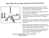
A. Crumple and insert 4 sheets of recovery
wadding into the body tube.
B. Roll the streamer tightly and insert it into
the tube with the shock cord. Then install the
nose cone into place.
C. Insert the rocket motor into the aft end of
the rocket (see instructions listed previously).
D. Insert and secure the engine igniter as
directed on the package the engines came with.
Countdown and Launch Procedure
Fly your rocket on a large eld that isn’t near
any power lines, trees, or low ying aircraft.
The larger the eld, the greater your chances of
recovering your rocket. The launch area around
the pad must be free of dry weeds and brown
grass. Launch only during calm weather with
very little or no wind and good visibility.
10. Remove the safety key from the launch
controller.
9. Slide the launch lugs over the launch rod to
place the rocket on the pad. The rocket should
slide freely over the rod.
8. Attach the micro-clips to the igniter. The clips
must not touch the other or the metal blast
deector.
7. Stand back from your rocket as far as the
launch wire allows (at least 5 meters - 15 feet).
6. Insert the safety key to arm the launch
system. The light (or buzzer) on the controller
should come on.
Give a loud countdown 5 ... 4 ... 3 ... 2 ... 1 ...
LAUNCH!
Push and hold the the button until the engine
ignites. Then remove the safety key and place
the safety cap on the launch rod.
Misre Procedure
Occasionally the igniter will burn, but the motor will fail to ignite. If this happens, the
cause is that the pyrogen on the igniter was not in contact with the engines propellant.
When an ignition failure occurs, remove the safety key from the launch controller and
wait 60 seconds before approaching the rocket. Remove the old igniter from the engine
and install a new one. Make sure that the igniter is insert fully into the engine and
touches the propellant. Secure the igniter as directed on the engine package and repeat
the countdown and launch procedure.
Always follow the NAR* Model Rocket Safety Code when launching model rockets.
*National Association of Rocketry
**Kevlar
®
is a brand name of E.I. DuPont for their selection of aramid bers. Only Du-
Pont makes Kevlar
®
Engine Alt. (ft) Alt. (m) Vel. (mi/hr) Vel. (m/s)
D12-7
E6-6
E15-10
E30-7
Motor
Dia. (mm)
F10-8
F20-7
F21-8
F23-7
G80-10
24
29
29
29
24
24
1348
3548
4459
5468
4030
2939
411
1082
1359
1666
1228
895
280
278
735
411
625
854
125
C11-7 24 751 229 197 88
124
E9-6 24 2141 652 359 161
328
24 2314 705 587 259
183
279
24 2894 882 595 266
29 2876 877 558 249
381
Apogee Aspire Motor Matrix
Fin
overlap
Fin Fin Fin
Launch Lug
Shock Cord Anchor
Tube Marking Guide
Sheet B - P/N 31049
/