Page is loading ...

Page
1
Colorado Springs, Colorado USA
web site: www.ApogeeRockets.com
The V-2 Conversion kit is another ne product from:
Kit #12111
Skill Level 4
Made in USA
P/N Item Name Qty
10091 AT-24/3.75” 1
10128 AT-33/17.75 (LC) 1
12358 CBD-33mm ⅛” Plywood (single) 1
13016 Coupler AC-33 (single) 1
13031 CR-18/24 (single) 1
13301 CR-24/33 ⅛” Plywood (single) 2
13279 CR-33 V-2 (LC) 1
13056 ¼” Launch Lug 1
24043 Crimped Engine Hook 1
29520 300# Kevlar X 8 ft 1
29602 Clay Nose Wt (⅓ stick) {30 grams} 1
29624 Wood Screw Eyebolt Size 9 1
29116 24” Plastic chute 1
31114 Instruction Sheet A 1
31115 V-2 Launching Instructions 1
47124 Clear Plastic Bag 6X24X2mil 1
p/n 31114
V-2 Conversion Kit
Parts List
Converts the Spacemonkey Models
V-2/A4 Plastic Model Kit into a Flying
Model Rocket
Supplies Needed
Spacemonkey Models V-2/A4 Plastic Model Kit
Pencil
Hobby Knife
Razor Saw
Wood Dowel or Stick (to spread glue inside tube)
Ruler
Sand Paper (220 and 400 Grit)
Wood Glue
Super Glue (Thick Viscosity)
Rocket engine to push in the engine block

Page
2
Skill Level 3: Average Skills Needed
This conversion kit is designed for the Spacemonkey Models V-2/A4 plastic model kit. It allows the rocket to be own
with 24mm diameter model rocket motors.
Changing a static model into a ying model is called “plastic model conversion” (PMC) by the National Association of
Rocketry (NAR). There is even a PMC contest event that you can y this rocket in.
The Spacemonkey Models V-2/A4 rocket is generally easy to convert to model rocket power because of the large
blow-molded body, and because the model has the nose cone separate towards the top of the body which leaves a lot of
room for the parachute.
This conversion kit should be assembled prior to the assembly of the plastic model rocket. That way when you’re
ready to add the ns and the other delicate details, there will be less of a chance to damage the plastic parts.
Step 5
Step 4
Step 3
V-2 Conversion Kit Assembly
Step 1 - Mark the short white body tube
2-¼ inches (57mm) from one end. Using
a hobby knife make a slit at the line about
1/8 inch (3mm) wide. Insert the end of the
engine hook into the slit as shown.
Step 2 - Take the green ring and glue it
inside the front end of the tube using wood
glue. You can use a rocket engine to push it
in until it butts against the metal engine hook
tang on the inside of the tube. Remove the
rocket engine casing immediately, and wipe
away the excess glue on both sides of the
engine block. Allow the glue time to dry.
Step 3 - Mark the engine mount tube
1/2 inch (13mm) from the end as shown.
Glue one of the wooden centering rings over
the tube and engine hook at this line using
wood glue. There is a small removable notch
on the inside of the ring that slips over the
engine hook.
Step 4 - Pass one end of the shock cord
through the remaining wooden centering
ring and tie the cord around the motor mount
tube. Cinch the cord tight to the tube. Run a
bead of wood glue around the forward end
of the motor mount tube. Slip the ring onto
the forward end of the motor mount tube so
that the front edge of the ring is even with
the end of the tube, and the shock cord is
running in the pre-cut slot. Pull the cord so
that the loop is tight up against the side of
the centering ring. Apply glue llets to both
sides of the centering rings and allow to dry.
Step 5 - Temporarily pass the shock
cord through the motor mount and out the
rear. This will keep it glue-free when glu-
ing the engine mount into the tube. Using a
wood dowel, apply wood glue 2-1/2 inches
(63.5 mm) inside the aft end of the 17.75
inch long body tube. (NOTE: The aft end is
the side that does not have the line around
the perimeter.) Also put glue on the aft ring
of the motor mount. Quickly and smoothly
2-1/4” (57mm)
1/2” (13mm)
Step 1
Step 2
1/2” (13mm)

Page
3
insert the motor mount tube into the aft end
of the body tube SO THE BACK RING IS
RECESSED AT LEAST ¼ INCH (6.5mm)
INSIDE THE END OF THE TUBE. Also,
the engine hook should NOT be in line with
the line on the tube. When the glue is dry,
pass the shock cord back through the motor
mount, so that it comes out the front end of
the rocket.
Step 6 - Take the red tube coupler and
place it on the plastic “aft nozzle insert” from
the Spacemonkey Models V-2 kit. Do not
glue it. Make sure it is straight on the nozzle
insert. Draw a line on the plastic with a pen-
cil, and remove the coupler tube.
Step 7 - Using a razor saw, cut the top
off the nozzle insert using the pencil line as
a guide. Clean up the edge with sandpaper.
The domed portion can be discarded.
Step 8 - Mark the middle of the aft edge
of the nozzle insert on the recessed portion
as shown. Anywhere around the ring is ne,
but this will now be the centerline of the n.
Step 9 - Test t the nozzle insert into the
back of the body tube from Step 5. The line
you made in Step 8 should align with the
pre-marked line on the outside of the body
tube. Also make sure the tube is straight on
the nozzle insert, and then glue it into place
using thick super glue.
Step 10 - Locate the laser-cut cardstock
centering ring. The side with the line etched
on it is the front side. Slide the ring over
the body tube and onto the front end of the
tube. The line on the ring should be aligned
with the lengthwise etched line of the tube,
and the front edge of the ring should be just
behind the perimeter line. Do not glue it yet.
Step 11 - This is a critical step, so be
sure to understand what has to occur before
you glue things into place. Slide the tube
into the rear of the blow-molded tube from
the plastic model kit. Refer to Step 7 of the
instruction sheet that came with the Space-
monkey Models V-2/A4 kit in how the nozzle
insert is aligned with the n location of the
blow molded tube. Looking from the front
side of the blow molded tube, check to see
if the paper centering ring is making good
contact with the inside edge of the blow
mold tube. When you are sure you under-
stand how everything ts together, remove
the parts and glue them together using thick
super glue.
Step 6
Step 7
Step 8
Step 9
Step 10
Step 11
Fin Line

Page
4
Step 12 - Screw and then glue the
screw-eye into the wooden bulkhead disk
using wood glue. Glue the assembly into
one end of the red tube coupler. The disk
should be just inside the end so that you can
put glue llets on both sides of the disk. Al-
low the glue to dry.
Step 13 (Optional) - Using a hobby
knife, cut a series of v-notches into the front
end of the tube coupler from the previous
step. Because the edge will bend inward
and conform better to the inside of the nose
cone, this will make a stronger glue joint
when the coupler is installed into the nose
cone in the next step.
Step 14 - Place the clay nose weight
into the front of the plastic nose cone from
the V-2 kit. Glue the coupler tube into the
nose using thick super glue. Make sure the
coupler is straight inside the nose cone.
While the glue is still wet, you can place
the other end of the coupler onto the blow
mold rocket tube to ensure the alignment is
straight. Allow the glue time to harden.
Step 15 - Tie the shock cord to the
screw eye on the base of the nose cone.
Step 16 - Holding the parachute at the
center of its top, pull the lines together to
even up the ends. Thread the three looped
lines through the screw eye on the base of
nose cone. Take the apex of the parachute
and pull it through all three string loops at
the same time and then pull to tighten the
knot. This securely attaches the parachute
to the rocket.
Step 17 - Draw a line down the side of
the cylindrical portion of the blow molded
part of the rocket. This line should not be in
line with the n lines on the bottom of the
tube, and should be straight along the cen-
terline of the rocket.
Glue the launch lug to the tube using
thick super glue. The location is not impor-
tant, as long as it is on the straight part, and
not the tapered portion of the rocket body.
At this point, you can complete and paint
the V-2/A4 rocket using the instruction sheet
from Spacemonkey Models.
Step 13
Step 14
Step 15
Step 16
Step 17
Step 12
Make sure lug won’t
be in-line with the ns

Page
5
Launch Supplies Needed
To launch your rocket you will need the following supplies:
• A model rocket launching system
• Flame resistant recovery wadding
• Recommended Rocket Engines: C11-3, D12-5
Rocket Preight
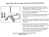
A. Crumple and insert 5 sheets of recovery wadding into the body tube.
B. Fold the parachute and insert it into the tube with the shock cord.
C. Insert the rocket motor into the aft end of the rocket.
D. Insert and secure the engine igniter as directed on the package the engines came with.
Countdown and Launch Procedure
Fly your rocket on a large eld that isn’t near any power lines, trees, or low ying aircraft; The larger the eld, the
greater your chances of recovering your rocket. The launch area around the pad must be free of dry weeds and brown
grass. Launch only during calm weather with very little or no wind and good visibility.
10. Remove the safety key from the launch controller.
9. Slide the launch lugs over the launch rod to place the rocket on the pad. The rocket should slide freely over the rod.
8. Attach the micro-clips to the igniter. The clips must not touch each other or the metal blast deector.
7. Stand back from your rocket as far as the launch wire allows (at least 5 meters - 15 feet).
6. Insert the safety key to arm the launch system. The light (or buzzer) on the controller should come on.
Give a loud countdown 5 ... 4 ... 3 ... 2 ... 1 ... LAUNCH!
Push and hold the button until the engine ignites. Then remove the safety key and place the safety cap on the launch
rod.
Misre Procedure
Occasionally the igniter will burn, but the motor will fail to ignite. If this happens, the cause is that the pyrogen on the
igniter was not in contact with the engines propellant. When an ignition failure occurs, remove the safety key from the
launch controller and wait 60 seconds before approaching the rocket. Remove the old igniter from the engine and install a
new one. Make sure that the igniter is insert fully into the engine and touches the propellant. Secure the igniter as directed
on the engine package and repeat the countdown and launch procedure.
Always follow the NAR* Model Rocket Safety Code when launching model rockets.
*National Association of Rocketry
**Kevlar
®
is a brand name of E.I. DuPont for their selection of aramid bers. Only DuPont makes Kevlar®
Need parts or accessories to go along with this kit?
Go online and order at www.ApogeeRockets.com or call us and
order at 719-535-9335. We’re available M-F: 9 am to 5 pm MST.
Recommended Items: Weblink
Rocket Engines www.ApogeeRockets.com/rocket_motors
Launch Controllers www.ApogeeRockets.com/launch_controllers
Launch Pad www.ApogeeRockets.com/Launch_Pads
p/n 31115 - V-2 Launching Instructions
V-2 Launching Instructions
/