Apogee 05056 Peregrine JR Operating instructions
- Type
- Operating instructions
Apogee 05056 Peregrine JR is a skill level 3 rocket kit, perfect for expanding your rocketry experience. With its smooth curves and sturdy build, it's an excellent base for creative designs. The dual-deploy feature allows for flying altimeters, eggs, or custom payloads, making it versatile for various experiments. The kit includes all necessary components, from fins and centering rings to parachutes and decals, for a quick and easy assembly. Fly it on D class 24mm motors for moderate-size fields or go over 2000' with F class motors for high-performance flights.
Apogee 05056 Peregrine JR is a skill level 3 rocket kit, perfect for expanding your rocketry experience. With its smooth curves and sturdy build, it's an excellent base for creative designs. The dual-deploy feature allows for flying altimeters, eggs, or custom payloads, making it versatile for various experiments. The kit includes all necessary components, from fins and centering rings to parachutes and decals, for a quick and easy assembly. Fly it on D class 24mm motors for moderate-size fields or go over 2000' with F class motors for high-performance flights.


-
 1
1
-
 2
2
-
 3
3
-
 4
4
-
 5
5
-
 6
6


Apogee 05056 Peregrine JR Operating instructions
- Type
- Operating instructions
Apogee 05056 Peregrine JR is a skill level 3 rocket kit, perfect for expanding your rocketry experience. With its smooth curves and sturdy build, it's an excellent base for creative designs. The dual-deploy feature allows for flying altimeters, eggs, or custom payloads, making it versatile for various experiments. The kit includes all necessary components, from fins and centering rings to parachutes and decals, for a quick and easy assembly. Fly it on D class 24mm motors for moderate-size fields or go over 2000' with F class motors for high-performance flights.
Ask a question and I''ll find the answer in the document
Finding information in a document is now easier with AI
Related papers
Other documents
-
Kestrel 05063 User manual
-
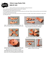 BLOTZ B10_ACC_410 Assembly Instructions
-
Estes 9723 User guide
-
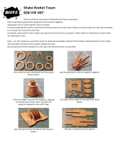 BLOTZ B28-VSF-007 Assembly Instructions
-
Aerotech SUMO Assembly And Operation Instructions Manual
-
-
-
Phoenix R/C Aerobatic Glider Assembly And Operation Manual
-
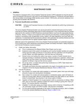 Cirrus SR20 Maintenance Manual
-


