Page is loading ...

CSXE SERIES
LED EXIT SIGN
IMPORTANT SAFEGUARDS
READ AND FOLLOW ALL SAFETY INSTRUCTIONS
● Do not mount near gas or electric heaters.
● Equipment should be mounted in locations and at heights where it will
not readily be subjected to tampering by unauthorized personnel.
● The use of accessory equipment is not recommended by
manufacturer and may cause an unsafe condition.
● Do not use equipment for anything other than intended use.
SAVE THESE INSTRUCTIONS
WARRANTY
5 YEAR LIMITED*
Manufacturer will replace or repair any components, which fail due to
manufacturer’s defects or workmanship, for a period of 5 years. The
warranty does not cover physical damage or abuse, and manufacturer
reserves the right to charge for such repairs if deemed necessary.
*Battery is covered separately by a 5 year pro-rated
warranty through manufacturer.
10070164 Rev 1
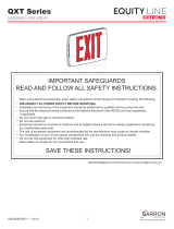
Fig. 3 Battery Connections and
DIP Switch Settings SELF-TEST & SELF-DIAGNOSTIC
INSTRUCTION MANUAL
(EXIT SIGNS WITH SEALED LEAD ACID, NiCd or NiMH BATTERIES)
KEEP THIS INSTRUCTION MANUAL FOR FUTURE REFERENCE
Operation
The purpose of this option is to provide self-testing
and self-diagnostic capabilities to the EXIT sign.
At predetermined intervals, the EXIT sign will auto-
matically switch into battery mode. Refer to the Self-
Test section of this page for timing details. The EXIT
sign will also perform various self-diagnostic tests of
the unit. Visual signaling will alert maintenance person-
nel to a fault of the EXIT sign electronics, batteryand/or
battery charger. The circuitry continuously monitors
the operating condition of the EXIT sign and battery
charging circuit/battery supply voltage. Refer to Self-
Diagnostic section of this page for fault reporting details.
LEDs
The EXIT sign is provided with a state-of-the art pulse
charging system for the battery. The yellow LED
(STEADY STATE) indicates that the charger is turned off.
The red LED (CHARGER ON) indicates that the battery is
under full charge. NOTE – the “STEADY STATE” and
“CHARGER ON” LEDs will toggle faster with a discharged
battery. A fully charged battery will cause the “STEADY
STATE” LED to be illuminated longer than the “CHARGER
ON” LED. The green “AC ON” LED indicates that normal
AC power is being supplied to the EXIT sign. The red
“UNIT ALERT” indicates whenever the self-diagnostic system
has detected a fault condition. An audible alert will sound on
units provided with an audible alarm (option “AA”) whenever
the self-diagnostic system has detected a fault condition.
Self-Diagnostic Features
Refer to the chart below when the “UNIT ALERT” LED is blinking.
Number of
Blinks Unit Fault Corrective Action
1 Battery is Disconnected Check battery connections
2 Battery Replace battery
3 Not Applicable Not Applicable
4 Charger Check battery then consult factory
5 Transfer (AC to DC) Check battery then consult factory
Use in accordance with local building codes.
Transformer Board Switch Setting and Location*
WARNING: LED LIGHT STRIP MUST BE CONNECTED TO
TRANSFORMER BOARD BEFORE APPLYING POWER
(DIP Switch Preset For 277VAC)
Follow these guidelines before applying power to the circuit board:
For proper operation of this power board,
the power wires and DIP switch are to be
connected as follows:
120 VAC application - white & black wires
- switch setting to left
277 VAC application - white & orange wires
- switch setting to right
*Non-Self diagnostic units only.
Red Wire (+) Black Wire (-)
• The EXIT sign will automatically switch to battery mode
every 28 days for a period of 5 minutes.
• The EXIT sign will automatically switch to battery mode
every 6 months for a period of 90 minutes.
Seft-Test Features
• Pressing the “TEST BUTTON” once will switch the unit into
battery mode for a period of 2 seconds.
• MANUAL TEST - Pressing the “TEST BUTTON” twice (in
rapid succession), will switch the unit to battery mode for a
period of 15 minutes. Pressing the “TEST BUTTON” once
while the unit is MANUAL TEST mode will cancel the manual
test and return to unit to normal AC power.
• RESET – Pressing the “TEST BUTTON” 3 times will reset the
red “UNIT ALERT” LED. If multiple faults are present, it may
be necessary to repeat this procedure for each remaining fault
indicated by the “UNIT ALERT” LED.
• On units provided with an audible alarm (option “AA”), pressing
and holding the “TEST BUTTON” for 5 seconds will disable the
alarm for 24 hours.
Test Button Features

Installation Instructions
WARNING: Shut off AC power to branch circuits to which units will be connected.
All wiring should be in accordance with the National Electrical Code and/or
local building codes.
Wall Mounting Instructions:
1. Remove appropriate knockouts from (4)
Back Mounting Plate and secure to outlet
box with field supplied screws (Fig. 1-1)
2. Slide (2) Main LED Housing over (4) Back
Mounting Plate as shown in Fig. 1-2 (a),(b).
3. Thread building supply wires through center
knockout (Fig. 1-1). Make electrical hookups
as follows:
120V AC 277V AC
White - Common White - Common
Black - 120V Orange - 277V
Green - Ground Green - Ground
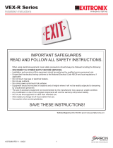
PARTS LIST:
(1) Power Supply Housing
(2) Main LED Housing
(3) Glass Panel
(4) Back Mounting Plate
(5) End Cap
(6) End Cap Screw
(7) Canopy
(8) Canopy Bracket
(9) Wing Nut (inside housing)
(10) 1 3/4” Screws
(11) Hex Nut
(12) Washer
(10) x 2
(12) x 2
(8)
(11) x 2
(7)
(9) (1)
(4)
(6)
(2)
(3)
Fig. 2
Ceiling or End Mounting Instructions:
1. Remove knockout in top of (1) Power Supply
Housing for ceiling mounting or side knockout
on (2) Main LED Housing for end mounting.
2. Install (10) Screws and (12) Washers into
(8) Canopy Bracket. Secure (10) Screws with
(11) Hex Nuts.
3. Thread building supply wires through center hole
and secure (8) Canopy Bracket to outlet box in
ceiling with field supplied screws.
4. Place (7) Canopy and EXIT sign on to (10) Screws
for mounting [top of (1) Power Supply Housing for
ceiling mount or side of (2) Main LED Housing for
end mount].
5. Fasten to (10) Screws using suppled (9) Wing Nuts.
6. Make appropriate AC connections as follows:
120V AC 277V AC
White - Common White - Common
Black - 120V Orange - 277V
Green - Ground Green - Ground
7. Adjust DIP switch on circuit board to the appropriate
position [for non-G2 units] (refer to Fig. 3). If provided with
batteries, make appropriate connections (Fig. 3).
8. Install (3) Glass Panel and secure (5) End Cap with (6) End
Cap Screw.
9. Refer to section “SELF-TEST...” for equipment with G2.
NOTE:
ENSURE AC ELECTRICAL CONNECTIONS ARE MADE WITHIN
JUNCTION BOX [Fig. 2-1 (a)].
4. Adjust DIP switch on circuit board to the appropriate
position [for non-G2 units] (refer to Fig. 3). If provided with
batteries, make appropriate connections (Fig. 3).
5. Install (3) Glass Panel and secure (5) End Cap with (6) End
Cap Screw.
6. Refer to section “SELF-TEST...” for equipment with G2.
NOTE:
ENSURE AC ELECTRICAL CONNECTIONS ARE MADE WITHIN
JUNCTION BOX [Fig. 1-1 (a)].
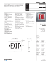
Fig. 1-2
Fig. 1-1
Fig. 2-1
(a) (b)
Orange (for 277V)
Black (for 120V)
White (Neutral)
Green (Ground)
Orange (for 277V)
Black (for 120V)
White (Neutral)
Green (Ground)
(4)
(4)
(2)
(5)
(a)
(a)
/