Page is loading ...

INSTRUCTIONS for Lithonia Lighting ECRG RD
Toggle the switchable button
to choose red or green illumination.
RED LENS
Remove or re-insert the red lens from/to face plate.
Secure the green lens to face plate.
GREEN LENS
Switchable
button
WARNING: FAILURE TO FOLLOW THESE INSTRUCTIONS AND
WARNINGS MAY RESULT IN DEATH, SERIOUS INJURY OR SIGNIFICANT
PROPERTY DAMAGE. For your protection, read and follow these warnings
and instructions carefully before installing or maintaining this equipment.
These instructions do not attempt to cover all installation and maintenance
situations. If you do not understand these instructions or additional
information is required, contact LITHONIA or your local LITHONIA distributor.
IMPORTANT SAFEGUARDS: When using electrical equipment, basic safety precautions should always be followed,
including the following:
WARNING: RISK OF ELECTRIC SHOCK - NEVER CONNECT TO,
DISCONNECT FROM, OR SERVICE WHILE EQUIPMENT IS ENERGIZED.
WARNING: RISK OF FIRE. Lamps are hot. Keep combustible
material away from hot parts. Observe lamp manufacture’s warnings,
recommendations and restrictions on lamp operation and maintenance. Make sure lamps are correctly installed.
NOTE: Max mounting height is 21.4 ft to achieve at least 1 ft-candle of illuminance in emergency mode.
LED COMBO EXIT & EMERGENCY LIGHT
READ AND FOLLOW ALL SAFETY INSTRUCTIONS
SAVE THESE INSTRUCTIONS
and deliver to owner after installation
CAUTION: The battery in this unit may not be fully charged. After electricity is connected to unit, let battery charge for at least
24 hours, then normal operation of this unit should take effect. To check, press the TEST button. The lamps on the unit should
turn on. (Refer to OPERATION BATTERY BACK UP for more testing information)
Do not use outdoors. Suitable for use in 0°C-40°C(32 104 indoor damp locations.
Consult local building code for approved wiring and installation.
Disconnect AC power before servicing and installation.
Do not mount near gas or electric heaters.
Do not use this equipment for anything other than its intended use.
The use of accessory equipment not recommended by the manufacturer will void product listing and warranty and may cause
an unsafe condition.
Any service on this equipment should be performed by qualified personnel only.
Equipment should be mounted in locations and at heights where it will not be subject to tampering by unauthorized personnel.
Use caution when servicing batteries.
Cap unused wires with enclosed wire nuts or other approved method.
Make sure wire terminations are secure and leads are properly tucked in appropriate wire channels.
°F- °F)

INSTRUCTIONS for Lithonia Lighting ECRG RD
SAVE THESE INSTRUCTIONS
and deliver to owner after installation
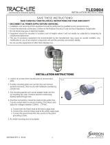
INSTALLATION INSTRUCTIONS(back mount):
1. De-energize the circuit at an industry standard junction box, (not included), where the exit sign is to be installed.
2. Remove EXIT stencil faceplate from housing. Remove RED lens from faceplate(see fig. A). Set aside.
3. Drill out the appropriate mounting pattern and the wire pass hole in the EXIT back plate to fit the junction box being used.
4. Feed the red, black and white wires through the center.
5. Remove side mounting hole plug on right side. Knockout lamp head mounting hole on left side with flathead screwdriver.
6. Feed blue and yellow lamp head wire through side lamp head mounting hole(Step 1). Attach first lamp head to housing by aligning tabs
on lamp head assembly to lamp head mounting slots on frame of housing (Step 2). Gently twirl lamp head clockwise to lock into place.
An audible click should be heard. Repeat to install remaining lamp head.
7. Feed lamp head wires in appropriate wire channel and connect lamp head leads to the exit sign lamp board.
8. Ensure fixture leads are fed through back plate and connect to AC power leads coming into the junction box.
9. Connect RED lead to HOT of the power supply from 120-277V. Connect the WHITE lead to the NEUTRAL of the supply.
10. HO only: make wiring connections to the appropriate remote lamp heads using the YELLOW(+) and the BLUE(-) remote leads on the
charger board. Cap off any UNUSED remote leads with wire nuts.
11. Fasten back plate to junction box cover.
12. Toggle the switchable to select GREEN, if applicable(see fig. C).
13. Connect battery only after continuous AC power can be provided to the unit.
14. Remove knockout chevron(s) on faceplate, as needed. Re-insert RED lens to faceplate (see fig. A)(or GREEN if applicable, see fig. B).
Secure EXIT stencil faceplate back onto housing.
NOTE: EXIT ships standard RED. Refer to Toggle Switch section for GREEN LED configuration.
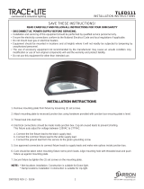
INSTALLATION INSTRUCTIONS(top or end mount):
1. De-energize the circuit at an industry standard junction box, (not included), where the exit sign is to be installed.
2. Remove EXIT stencil faceplate(see fig. A) from housing. Remove RED lens from faceplate. Set aside.
3. Remove the canopy kit, hardware pack and mounting plate from inside the EXIT and set aside.
4. Remove the mounting hole plug on the top or either side of the frame.
5. Place the canopy nose through the mounting hole until the side of the frame touches the canopy. Lock the frame onto the
canopy by sliding the frame in a direction parallel to the canopy length toward the narrow end of the mounting hole. Slide the
frame until both snaps engage the canopy nose preventing any motion back out of the hole.
6. Feed the red, black and white wires through center of mounting canopy hole.
7. Remove side mounting hole on right side. Knockout lamp head mounting hole on left side with flathead screwdriver.
8. Feed blue and yellow lamp head wire through side lamp head mounting hole (Step 1). Attach first lamp head to housing by
aligning tabs on lamp head assembly to lamp head mounting slots on frame of housing(Step 2). Gently twirl lamp head clockwise
to lock into place. An audible click should be heard. Repeat to install remaining lamp head.
9. Feed lamp head wires in appropriate wire channel and connect lamp head leads to the exit sign lamp board.
10. Ensure fixture leads are fed through mounting canopy and connect to AC power leads coming into the junction box.
11. Connect RED leads to HOT of the power supply from 120-277V.
Connect the WHITE lead to the NEUTRAL of the supply.
12. When applicable, make wiring connections to the appropriate remote lamp heads using the YELLOW(+) and the BLUE(-) remote
leads on the charger board. Cap off any UNUSED remote leads with wire nuts.
13. Secure the EXIT canopy to the steel mounting plate using the screws provided and fasten to junction box.
14. Toggle the switchable to select GREEN, if applicable(see fig. C).
15. Connect battery only after continuous AC power can be provided to the unit.
16. Remove knockout chevron(s) on faceplate, as needed. Re-insert RED lens to faceplate (see fig. A)(or GREEN if applicable, see fig. B).
Secure EXIT stencil faceplate back onto housing.
17. Secure faceplate(s) to housing.

3
3
Red 120-277V
Red 120-277V
HO
INSTRUCTIONS for Lithonia Lighting ECRG RD
Part No. 912-00195-001,
Rev A Prelim 10.19.2020
SAVE THESE INSTRUCTIONS
and deliver to owner after installation
/