Page is loading ...

EMERGENCY LED EXIT SIGN
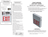
INSTRUCTIONS for Lithonia Lighting EXRG
Remove or re-insert the red lens from/to face plate.
RED LENS GREEN LENS
Secure the green lens to face plate.
Toggle the switchable button
to choose red or green illumination.
Switchable
button
READ AND FOLLOW ALL SAFETY INSTRUCTIONS
SAVE THESE INSTRUCTIONS
and deliver to owner after installation
WARNING: FAILURE TO FOLLOW THESE INSTRUCTIONS AND
WARNINGS MAY RESULT IN DEATH, SERIOUS INJURY OR SIGNIFICANT
PROPERTY DAMAGE. For your protection, read and follow these warnings
and instructions carefully before installing or maintaining this equipment.
These instructions do not attempt to cover all installation and maintenance
situations. If you do not understand these instructions or additional
information is required, contact LITHONIA or your local LITHONIA distributor.
IMPORTANT SAFEGUARDS: When using electrical equipment, basic safety precautions should always be followed, including
the following:
WARNING: RISK OF ELECTRIC SHOCK - NEVER CONNECT TO,
DISCONNECT FROM, OR SERVICE WHILE EQUIPMENT IS ENERGIZED.
WARNING: RISK OF FIRE. Lamps are hot. Keep combustible
material away from hot parts. Observe lamp manufacture’s warnings,
recommendations and restrictions on lamp operation and maintenance. Make sure lamps are correctly installed.
CAUTION: The battery in this unit may not be fully charged. After electricity is connected to unit, let battery charge for at least
24 hours, then normal operation of this unit should take effect. To check, press the TEST button. The lamps on the unit should
turn on. (Refer to OPERATION BATTERY BACK UP for more testing information)
Do not use outdoors. Suitable for use in 0°C-40°C(32°F-104°F) indoor damp locations.
Consult local building code for approved wiring and installation.
Disconnect AC power before servicing and installation.
Do not mount near gas or electric heaters.
Do not use this equipment for anything other than its intended use.
The use of accessory equipment not recommended by the manufacturer will void product listing and warranty and may cause
an unsafe condition.
Any service on this equipment should be performed by qualified personnel only.
Equipment should be mounted in locations and at heights where it will not be subject to tampering by unauthorized personnel.
Use caution when servicing batteries.
Cap unused wires with enclosed wire nuts or other approved method.
Make sure wire terminations are secure and leads are properly tucked in appropriate wire channels

Recommended 4"
standard junction
INSTRUCTIONS for Lithonia Lighting EXRG
1. Remove EXIT stencil faceplate from housing. Remove RED lens from faceplate (see Fig. A). Set aside.
2. Drill or knock out appropriate knockouts on back plate to fit junction box mounting points.
3. Drill or knock out center hole in back plate for EXIT supply wire leads.
4. Route EXIT input wires though center hole of the back plate and make wiring connection. For 120V, use black and white
wires and for 277V, use red and white wires.
5. Secure back plate to junction box (hardware not included).
6. Toggle the switchable to select GREEN, if applicable (see Fig. C).
7. Connect battery (EL models only).
8. Remove knockout chevron(s) on faceplate, as needed. Re-insert RED lens to faceplate (see Fig. A) (or GREEN if applicable,
see Fig. B). Secure EXIT stencil faceplate back onto housing.
9. Apply continuous AC power, LED indicator will be RED.
10. EL only: Press "TEST" button to check operation. (See OPERATION BATTERY BACK UP for testing procedures).
WALL MOUNT INSTALLATION
CEILING OR END MOUNT INSTALLATION
1. Remove EXIT stencil faceplate from housing. Remove RED
lens from faceplate (see Fig. A). Set aside.
2. Place screws (provided) in holes on the canopy.
3. Remove the desired mounting hole plug located on the
frame of the sign. For ceiling mount, hole plug will be
located on the top of the housing. For end mount, hole
plug will be located on the side of the housing.
4. Place canopy tab through the mounting hole of the
housing until the flat portion of the canopy is touching the
housing frame. Lock the canopy into place by sliding the
canopy, without turning, toward smaller end of the
mounting hole until the tab is fully engaged and locked
into place. Once canopy is in the locked position there will
not be any side-to-side movement of the canopy.
5. Route EXIT input wires through canopy and through metal
mounting plate.
6. Make wiring connection. For 120V, use black and white
wires and for 277V, use red and white wires. WARNING:
Properly insulate the unused lead with a wire nut
(provided) or other approved means.
7. Push wire connections into the J-Box. Secure mounting
plate to junction box (hardware not included).
8. Secure the canopy to the steel mounting plate with
screws installed in step 2.
9. Toggle the switchable to select GREEN, if applicable (see Fig. C).
10. Remove knockout chevron(s) on faceplate, as needed. re-insert
RED lens to faceplate (see Fig. A)(or GREEN if applicable, see
Fig. B). Secure EXIT stencil faceplate back onto housing.
11. Connect battery (EL models only).
12. Apply continuous AC power, LED indicator will be RED.
13. EL only: Press "TEST" button to check operation. (See
OPERATION BATTERY BACK UP for testing procedures).
WIRING DIAGRAMS:
SAVE THESE INSTRUCTIONS
and deliver to owner after installation
NOTE: EXIT ships standard RED. Refer to Toggle Switch section for GREEN LED configuration.

INSTRUCTIONS for Lithonia Lighting EXRG
800-705-SERV (7378)
techsupport-emergency@acuitybrands.com
Part No. 912-00194-001,
Rev A Prelim 10.19.2020
OPERATION (BATTERY BACKUP)
1. Apply AC power to the unit. The LED indicator will be RED.
2. After the battery has been left to charge for 24 hours, test the unit by pushing the switch. The LED indicator turns
OFF and the LED board stays ON.
3. When the switch is released, the LED indicator turns back to RED and the LED board stays ON.
MAINTENANCE
Caution: Always turn off AC power to the equipment before servicing. Serving should be performed only
by a qualified service technician. Use only MANUFACTURER supplied replacement parts.
BATTERY: The battery supplied with the EL model requires no maintenance. However, it should be tested periodically
and replaced when it no longer operates the connected sign for the duration of a 30-second or 90-minute
test. The battery supplied in this sign has a typical life of 5 years when used in a normal ambient temperature
of 72°F.
SAVE THESE INSTRUCTIONS
In accordance with NFPA 101 (current Life Safety Code), documented testing of your emergency lighting system
must be tested monthly for a minimum of 30 seconds and annually for 90 minutes. Refer to your local codes for any
additional requirements that may apply.
SAVE THESE INSTRUCTIONS
and deliver to owner after installation
/