Page is loading ...

Ceiling and End Mounting
1. Remove the faceplate by removing the screw from the bottom of the unit, then slide
the faceplate down and set aside.
2. Remove both the circular and rectangle knockouts from either the top or side of
the unit.
3. Slide one square nut from the threaded stem rod hardware into the slot located
inside the housing.
4. Line up the canopy with the knockout holes and push the clip through rectangular
knockout to lock into place.
5. Feed the AC supply and ground wires from inside the unit through the nut, threaded
stem, canopy, and mounting plate.
6. Screw the threaded stem rod, lock washer, and the square nut through
the canopy and unit, ensure the hardware is tightened securely.
7. Determine the position and direction for the emergency sign. Then using
the round mounting plate, align the unit with the junction box.
INSTALLATION INSTUCTIONS
800.533.3948 • www.barronltg.com
1
INSTALLATION INSTUCTIONS
10070182 Rev 3 - 02/19
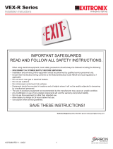
IMPORTANT SAFEGUARDS
READ AND FOLLOW ALL SAFETY INSTRUCTIONS.
When using electrical equipment, basic safety precautions should always be followed including the following:
• DISCONNECT AC POWER SUPPLY BEFORE SERVICING.
• Installation and servicing of this equipment should be performed by qualified service personnel only.
• Ensure that the electrical wiring conforms to the National Electrical Code NEC® and local regulations if applicable.
• Do not mount near gas or electrical heaters.
• Equipment should be mounted in locations and at heights where it will not be readily subjected to tampering by
unauthorized personnel.
• The use of accessory equipment not recommended by the manufacturer may cause an unsafe condition.
• Any modification or use of non-original components will void the warranty and product liability.
• Do not use this equipment for other than intended use.
SAVE THESE INSTRUCTIONS!
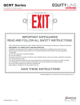
VEX-S SERIES
Fig. 1
Fig. 2

8. Make electrical connections: see Electrical Connection sections.
9. Mount the sign to the junction box with (2) #8-32 screws (provided) and tighten securely.
10. Remove the chevron(s) from the EXIT legend(s) if necessary.
11. Attach the battery jumper wire (for battery backup unit) to the PC board only after continuous AC power can be
supplied to the unit.
12. Slide the faceplate back into place and replace the screw.
Wall Mounting
1. Remove the faceplate by removing the screw from the bottom of the unit, then slide the faceplate down and set
aside.
2. Remove knockouts from the backplate that match the junction box.
3. Route the units input wires through the center wire access hole of the backplate and make the wiring connections.
4. Make electrical connections: see Electrical Connection sections.
5. Push the wires against the back of the sign to minimize any chance of the wires interfering with the illumination of
the letters.
6. Mount the sign to the junction box with (2) #8-32 screws (provided)
and tighten securely.
7. Remove the chevron(s) from the EXIT legend(s) if necessary.
8. Attach the battery jumper wire (for battery backup unit) to the PC board.
9. Slide the faceplate back into place and replace the screw.
Electrical Connections
All electrical connections should be made inside the junction box.
Make Electrical Connections as follows:
120V AC 277V AC
White - Common White - Common
Black - 120VAC Red/Orange - 277VAC
Green - Ground Green - Ground
Note: Cap unused leads to prevent shorting.
800.533.3948 • www.barronltg.com
2
INSTALLATION INSTUCTIONS
10070182 Rev 3 - 02/19
VEX-S SERIES
Battery Backup
AC Only
/