Page is loading ...


D8M-FMC User
Manual
www.terasic.com
September 14, 2022
Chapter 1 P16E-FMCP Development Kit ................................................................ 1
1.1 Package Contents ........................................................................................................................ 1
1.2 P16E-FMCP System CD ............................................................................................................ 1
1.3 Getting Help ............................................................................................................................... 2
Chapter 2 Introduction of the P16E-FMCP Board .................................................... 3
2.1 Features ....................................................................................................................................... 4
2.2 Block Diagram of the P16E-FMCP Board ................................................................................. 4
2.3 2.2 Connectivity ......................................................................................................................... 5
Chapter 3 PCIe Endpoint Example Codes .............................................................. 7
3.1 Demo Setup with Apollo Agilex SOM on Windows .................................................................. 7
3.2 Demo Setup with Apollo S10 ................................................................................................... 10
Chapter 4 Appendix ............................................................................................. 12
4.1 Revision History ....................................................................................................................... 12
4.2 Copyright Statement ................................................................................................................. 12

D8M-FMC User
Manual
1
www.terasic.com
September 14, 2022
Chapter 1
P16E-FMCP Development Kit
he P16E-FMCP FMC+ daughter card allows the FPGA boards equipped with the FMC+
connector and support the PCIe interface to connect with the PC.
The P16E-FMCP daughter card is purposely designed to convert transceiver channels of FMC+
connector to PCIe Edge. It can support up to PCIe Gen 4 x16. Developers can connect the PCIe
Edge of P16E-FMCP to a PC slot through a PCIe 4.0 X16 Riser Cable.
The kit also provides complete demo source codes for the P16E-FMCP working with different FPGA
development kits with FMC+ connectors.
1.1 Package Contents
Figure 1-1 The P16E-FMCP package contents
1.2 P16E-FMCP System CD
The P16E-FMCP System CD contains all the documents and supporting materials associated with
P16E-FMCP, including the user manual, reference designs, and device datasheets. Users can
download this system CD from the link: http://p16e-fmcp.terasic.com/cd.
T
The P16E-FMCP package includes:
One P16E-FMCP module
Screw & Copper Pillar Package
System CD Download Guide

D8M-FMC User
Manual
2
www.terasic.com
September 14, 2022
1.3 Getting Help
Here are the addresses where you can get help if you encounter any problems:
Terasic Technologies
No.80, Fenggong Rd., Hukou Township, Hsinchu County 303035. Taiwan
Email: support@terasic.com
Tel.: +886-3-575-0880
Website:http://www.terasic.com

D8M-FMC User
Manual
3
www.terasic.com
September 14, 2022
Chapter 2
Introduction of the P16E-FMCP Board
This chapter describes the architecture and configuration of the P16E-FMCP Board including block
diagram and components related.
Figure 2-1 The P16E-FMCP Board PCB and Component Diagram of top side
The Photographs of the P16E-FMCP are shown in Figure 2-1 and Figure 2-2. They depict the
layout of the board and indicates the location of the connectors and the key components on the top
and bottom side.

D8M-FMC User
Manual
4
www.terasic.com
September 14, 2022
Figure 2-2 The P16E-FMCP Board PCB and Component Diagram of bottom side
The following hardware is provided on the board:
PCIe Clock Buffer Si53152
A Push Button for PCIe Reset
FMC+ Connector (HPC)
2.1 Features
The P16E-FMCP daughter card is purposely designed to convert transceiver channels of FMC+
connector to PCIe Edge. It can support up to PCIe Gen 4 x16. Developers can connect the PCIe
Edge of P16E-FMCP to a PC slot through a PCIe 4.0 X16 Riser Cable.
A FPGA board to compatible with P16E-FMCP, it must be:
Provide MFC+ connector. Note, FMCP_VAJD is not required if SMB bus is not used.
GBTCLK_M2C in FMC+ connector must connect to the reference clock pins of FPGA PCIe
End-point IP.
RES0 in FMC+ connector must connect to the reset pin of FPGA PCIe End-point IP.
DP[15:0] in FMC+ connector must connect to the transceiver pins of FPGA PCIe End-point IP.
2.2 Block Diagram of the P16E-FMCP Board
Below Figure 2-3 shows the P16E-FMCP Block Diagram. The PCIe clock is coming from PCIe
Edge and connect to PCIe clock buffer Si53125 as a input clock. The Si53125 output two PCIe clocks
to the GBTCLK_M2C pins of FMC+ connector. In the FPGA board, the PCIe clock signal must
connect to the reference clock pins of the FPGA PCIe IP.
The PCIe reset signal is coming from PCIe edge, and directly connect to the RES0 side-band pin of
FMC+ connector. In the FPGA board, the RES0 must connect to the reset pin of FPGA PCIe IP. On
board push button PB1 can be used to trigger a PCIe reset signal to FMC+ RES0. It is designed for
debug prupuse.
PCIe x16 pair high speed lanes are directly connected between PCIe Edge and FMC+ Gigabit
Transceiver data pairs. Each lane provides speeds up to 16GT/s for supporting PCIe Gen4.

D8M-FMC User
Manual
5
www.terasic.com
September 14, 2022
Figure 2-3 Block diagram of P16E-FMCP Board
2.3 Connectivity
Terasic P16E-FMCP is able to connect on to FPGA board equipped with FMC+ connector. The Below
pictures Figure 2-4 and Figure 2-5 show the connections with two different Terasic FPGA Boards:
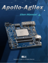
Figure 2-4 Connect the P16E-FMCP to Apoll-Agilex FMC+ port


D8M-FMC User
Manual
7
www.terasic.com
September 14, 2022
Chapter 3
PCIe Endpoint Example Codes
This chapter provides PCIe examples for users to get started using the P16E-FMCP board. Terasic
Apollo-Agilex SOM or Apollo-S10 FPGA board is required to perform the demonstration. Also, a PCIe
Riser Cable is required to P16E-FMCP to connect to your PC easily.
3.1 Demo Setup with Apollo Agilex SOM on Windows
Agilex Hard IP for PCI Express with Avalon-MM DMA is used to implement a PCIe Endpoint Gen4
x16 demonstration. For the design details, please the PCI Express Reference Design chapter in
Terasic DE10-Agilex User Manual.
Figure 3-1 shows the architecture of the PCIe end-point demo.
Figure 3-1 Architecture of PCIe End-point Gen4 x16 Demonstration
Project Information
The project is located on the folder <CD>\Demonstration\Agilex_SOM. Below tables describe the

D8M-FMC User
Manual
8
www.terasic.com
September 14, 2022
project detail information.
Items
Sub folder
Quartus Project Source (Quartus Pro 21.4)
PCIe_Fundamental
FPGA Configure File
PCIe_Fundamental\demo_batch
Windows Application Execution file
PCIe_Fundamental\demo_batch\windows_ap
p
Windows PCIe Driver
PCIe_SW_KIT\Windows\PCIe_Driver
Windows Library
PCIe_SW_KIT\Windows\ PCIe_Library
Windows Application Source (VC 2019)
PCIe_SW_KIT\Windows\PCIE_FUNDAMENT
AL
System Requirements
The following items are required to setup PCIe End-point demonstration:
P16E-FMCP board x1
Apollo-Agilex Board x1
PCIe Riser Cable x1
PC with PCIe x16 Port x1
Hardware Setup
Please follow the steps below to set up the hardware as shown in Figure 3-2
1. Install P16E-FMCP on the FMC+ connector of Apollo-Agilex.
2. Connect the PCIe edge of P16E-FMCP to the PCIe Slot of PC by a PCIe riser cable.

D8M-FMC User
Manual
9
www.terasic.com
September 14, 2022
Figure 3-2 Hardware Setup for Apollo-Agilex Demo
Demo Setup Operation
Please follow the steps below to perform the demonstration. For details, please the PCI Express
Reference Design chapter in Terasic DE10-Agilex User Manual. The manual can be download
from the Resource website of the DE10-Agilex board.
1. Power on Apollo-Agilex.
2. Configure FPGA by execute test.bat on the system CD folder:
Demonstration\Apollo_SOM\PCIe_Fundamental\demo_batch
3. Power on PC.
4. Make sure Windows detected the PCIe FPGA board.
5. Install the PCIe Driver located in the system CD:
Linux: Demonstration\Apollo_SOM\PCIe_SW_KIT\Linux\PCIe_Driver
Windows: Demonstration\ Apollo_SOM \PCIe_SW_KIT\Windows\PCIe_Driver
6. Execute the Windows application PCIE_FUNDAMENTAL.exe located on the CD folder:
Linux: Demonstration\ Apollo_SOM \PCIe_Fundamental\demo_batch\linux_app
Windows: Demonstration\ Apollo_SOM \PCIe_Fundamental\demo_batch\windows_app
7. A console mode manual will appears. Select DMA Memory Test to perform DMA test.

D8M-FMC User
Manual
10
www.terasic.com
September 14, 2022
3.2 Demo Setup with Apollo S10
Stratix 10 Hard IP for PCI Express with Avalon-MM DMA IP is used to implement the PCIe End-point
Gen3x16 demonstration. The demo can be executed on both Linux and Windows. For details, please
refer to the PCI Express Reference Design Section in Terasic DE10-Pro User Manual. The manual
can be download from http://de10-pro.terasic.com/cd.
Project Information
The project is located on the folder <CD>\Demonstration\Agilex_S10. Below tables describe the
project detail information.
Items
Sub folder
Quartus Project Source (Quartus Pro 19.1)
PCIe_Fundamental
FPGA Configure File
PCIe_Fundamental\demo_batch
Linux Application Execution file
PCIe_Fundamental\demo_batch\linux_app
Windows Application Execution file
PCIe_Fundamental\demo_batch\windows_app
Linux PCIe Driver
PCIe_SW_KIT\Linux\PCIe_Driver
Linux Library
PCIe_SW_KIT\ Linux \ PCIe_Library
Linux Application Source
PCIe_SW_KIT\ Linux \PCIE_FUNDAMENTAL
Windows PCIe Driver
PCIe_SW_KIT\Windows\PCIe_Driver
Windows Library
PCIe_SW_KIT\Windows\ PCIe_Library
Windows Application Source (VC 2019)
PCIe_SW_KIT\Windows\PCIE_FUNDAMENTAL
System Requirements
The following items are required to setup PCIe End-point demonstration:
P16E-FMCP board x1
Apollo-S10 Board x1
PCIe Riser Cable x1
PC with PCIe x16 Port x1
Hardware Setup
Please follow the steps below to set up the hardware as shown in Figure 3-3
1. Install P16E-FMCP on the FMC+ connector of Apollo-S10.
2. Connect the PCIe edge of P16E-FMCP to the PCIe Slot of PC by a PCIe riser cable.

D8M-FMC User
Manual
11
www.terasic.com
September 14, 2022
Figure 3-3 Hardware for Apollo S10
Demo Setup Operation
Please follow the steps below to perform the demonstration. For details, please the PCI Express
Reference Design chpater in Terasic DE10-Pro User Manual. The manual can be download from
http://de10-pro.terasic.com/cd.
1. Power on Apollo-S10.
2. Configure FPGA by execute test.bat on the system CD folder:
Demonstration\Apollo_S10\PCIe_Fundamental\demo_batch
3. Power on PC.
4. Make sure Windows detected the PCIe FPGA board.
5. Install the PCIe Driver located in the system CD:
Linux: Demonstration\Apollo_S10\PCIe_SW_KIT\Linux\PCIe_Driver
Windows: Demonstration\Apollo_S10\PCIe_SW_KIT\Windows\PCIe_Driver
6. Execute the Windows application PCIE_FUNDAMENTAL.exe located on the CD folder:
Linux: Demonstration\Apollo_S10\PCIe_Fundamental\demo_batch\linux_app
Windows: Demonstration\Apollo_S10\PCIe_Fundamental\demo_batch\windows_app
7. A console mode manual will appears. Select DMA Memory Test to perform DMA test.

/