Page is loading ...


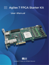
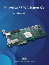
Apollo Agilex
User Manual
2
www.terasic.com
May 18, 2023
Contents
Chapter 1 Overview .................................................................................. 4
1.1 General Description .............................................................................. 4
1.2 Board Layout ......................................................................................... 5
1.3 Key Features ......................................................................................... 7
1.3. Block Diagram ....................................................................................... 9
1.4. Mechanical Specifications ..................................................................... 9
1.5. Power Requirement ............................................................................ 10
1.6. Connectivity ......................................................................................... 12
Chapter 2 Board Component ................................................................ 14
2.1 Configuration Interface ........................................................................ 14
2.2 Setup and Status Components ........................................................... 18
2.3 General User I/O ................................................................................. 24
2.4 Micro SD Card Socket ......................................................................... 26
2.5 FMC Connector ................................................................................... 26
2.6 FMC+ Connector ................................................................................. 38
2.7 Clock Circuit ........................................................................................ 51
2.8 USB to UART ...................................................................................... 54

Apollo Agilex
User Manual
3
www.terasic.com
May 18, 2023
2.9 DDR4 SODIMM Socket ....................................................................... 57
2.10 USB 2.0 OTG PHY .............................................................................. 69
2.11 Gigabit Ethernet .................................................................................. 70
2.12 2x6 GPIO Header ................................................................................ 71
2.13 QSFP28 Port ....................................................................................... 73
Chapter 3 Dashboard GUI...................................................................... 77
3.1 Setup for the Dashboard GUI .............................................................. 77
3.2 Run Dashboard GUI ............................................................................ 78
Chapter 4 Transceiver Verification ....................................................... 87
4.1 Function of the Transceiver Test Code ................................................ 87
4.2 Hardware Required ............................................................................. 87
4.3 Execute the Test Code ........................................................................ 88
Chapter 5 Install Driver for the Board .................................................. 91
5.1 Install the USB Blaster II Driver ........................................................... 91
5.2 Install USB to UART Driver ................................................................. 91
Chapter 6 Additional Information ......................................................... 97
6.1 Getting Help ........................................................................................ 97

Apollo Agilex
User Manual
4
www.terasic.com
May 18, 2023
Chapter 1
Overview
his chapter provides an overview of the Apollo Agilex SoM Board and
installation guide.
1.1 General Description
Designed for high-performance AI-enabled edge solutions and HPC solutions, Apollo
Agilex SOM packs unbeatable performance optimization and provides highest
real-time compute/watts for edge AI applications.
Apollo Agilex SOM takes advantage of the latest Intel® Agilex® SoC with 1400K logic
elements to obtain performance and power breakthrough (with up to 40% lower power
than Stratix 10 series). Combining high-end hardware interfaces such as two
high-capacity and high-bandwidth DDR4 SO-DIMM Sockets, on-board QSFP28
connector, PCIe Gen 4x16 up to 25.8 Gbps/ch with carrier, on-board USB-Blaster II,
and FMC/FMC+ connectors for I/O expansion, the board delivers more than 2X the
performance of previous generation development kits.
T


Apollo Agilex
User Manual
7
www.terasic.com
May 18, 2023
Figure 1-3 Apollo Agilex board bottom
1.3 Key Features
The following hardware is implemented on the Apollo Agilex board:
FPGA Device
Intel® Agilex® SoC FPGA : AGFB014R24B1E1V/AGFB014R24B2E2V
1,400K logic elements (LEs)
229 Mbits embedded memory(M20K)
96 transceivers (up to 28.3Gbps)
11,520 18-bit x 19-bit multipliers
5,760 Variable-precision DSP blocks
FPGA Configuration

Apollo Agilex
User Manual
8
www.terasic.com
May 18, 2023
On-Board USB Blaster II (UB2) for FPGA programming and Debug
AS Mode configuration from QSPI Flash
FPGA Fabric
1024Mbit QSPI Flash (EPCQL1024 Compliant)
Two DDR4 SO-DIMM Sockets (each with 72-bit ECC, speed up to 26
66MT/s, and size up to 16GB)
Onboard QSFP28
One FMC+ Connector
One FMC Connector
Two 50Mhz Single-ended
1.2V 2x6 GPIO header
LED x2, Button x2, DIP Switch x2, CPU Reset
HPS(Hard Processor System) Fabric
Quad-core 64 bit ARM Cortex-A53 MPCore* processor
MicroSD Socket
Gigabit Ethernet PHY with RJ45
USB OTG PHY with Micro USB Connector
UART to USB with Mini USB Connector
LED x1, Button x1, Cold Reset Button
3.3V 2x6 GPIO Expansion header for GPIO/SPI/I2C/UART
RTC
Dashboard System
Input Power Monitor
FPGA and Board Temperature Monitor
Fan Control and Monitor
Auto Fan Speed
Auto Shutdown
Power Source
12V from 2x4 PCIe connector

Apollo Agilex
User Manual
9
www.terasic.com
May 18, 2023
12V from Samtec connector (reserved for carrier board)
1.3. Block Diagram
Figure 1-4 shows the block diagram of the Apollo Agilex board. To provide maximum
flexibility for the users, all key components are connected to the Agilex® SoC FPGA
device. Thus, users can configure the FPGA to implement any system design.
Figure 1-4 Block diagram of the Apollo Agilex board
1.4. Mechanical Specifications
Figure 1-5 shows the Mechanical Layout of Apollo Agilex board. The unit of the
Mechanical Layout is millimeter (mm).

Apollo Agilex
User Manual
10
www.terasic.com
May 18, 2023
Figure 1-5 Mechanical layout
1.5. Power Requirement
Stand-alone mode
When the Apollo Agilex board is used in stand-alone mode, users can use the 12
V ATX power provided in the kit to connect to the 8-pin 12V ATX power connector
(See Figure 1-6) of the Apollo Agilex.

Apollo Agilex
User Manual
11
www.terasic.com
May 18, 2023
Figure 1-6 8-Pin 12V ATX Power Connector
Connect to the based board
If user wants use the Apollo Agilex board as the module board and connect it to the
carrier board. The carrier board needs to provide at least 12V 15A power to the J10
power connector (See Figure 1-7) of the Apollo Agilex board. Please note that the
12V and 3.3V of the FMC and FMC + connector are provided by the Apollo Agilex
board, the carrier board does not need to provide these powers. For part number of
the connector connected to J10, please refer to Table 1-1 in the section 1.7.

Apollo Agilex
User Manual
12
www.terasic.com
May 18, 2023
Figure 1-7 Power connector for connecting based board
1.6. Connectivity
Most of the FPGA I/O on the FMC and FMC+ connectors of the Apollo Agilex board
are 1.2V standard (*1). Therefore, if users want to connect FMC/FMC+ daughter
cards or other motherboards to the Apollo Agilex board, users need to pay special
attention to whether they directly support the 1.2V I/O standard.
If user wants to make their owned carrier board to connect with the Apollo Agilex
board, there are three connectors are needed to be used, they are FMC +, FMC and
Power connector (See 錯誤! 找不到參照來源。). The following table lists the
manufacturer and manufacturer part numbers of the three connectors that can match
with the connectors of the Apollo Agilex board.
*1 : The HPC part of the FMC+ pins can be set 1.5 or 1.2V I/O standard, please refer
to section 2.2 “FMC_VCCIO Select Header” part for detailed.
Table 1-1 Part Number of the connector on the Apollo Agilex board
Connector
Apollo Agilex Board’s Part
Number
Carrier Board’s
Part Number
FMC
J2
Samtec : ASP-134488-01


Apollo-Agilex SoM
User Manual
14
www.terasic.com
May 18, 2023
Chapter 2
Board Component
his chapter introduces all the important components on the Apollo Agilex.
2.1 Configuration Interface
This section describes the configuration mode for Agilex SoC FPGA available on the
Apollo Agilex. The peripheral circuits and usage scenarios for each mode will be listed.
As shown in Figure 2-1, the mode select pin of the FPGA on the Apollo Agilex board
has been set to Active Serial (AS) mode using resistors. Thus, the Apollo Agilex
board supports the following configuration modes:
JTAG Mode (Configure the FPGA using the on-board USB Blaster II).
Active Serial (AS) mode
Users can use these modes to configure the FPGA or HPS (Hardware Process System)
fabric in the Agilex SoC FPGA and make the FPGA to run the user's logic or boot the
HPS to run the OS.
Below we will introduce more detailed information of AS mode, as well as other
configuration information.
T

Apollo-Agilex SoM
User Manual
15
www.terasic.com
May 18, 2023
Figure 2-1 The MSEL pin setting
Active Serial (Fast) mode
In AS mode, the FPGA's configuration file is stored in the QSPI flash. The Secure
Device Manager (SDM) in Agilex SoC FPGA is responsible for the entire AS mode
process and interface. The SDM will load the initial configuration firmware from the
QSPI flash to configure the FPGA including FPGA I / O and core configuration. HPS
part of the boot can also be completed in this mode. Figure 2-2 shows the architecture
of the AS mode of the Apollo Agilex board.

Apollo-Agilex SoM
User Manual
16
www.terasic.com
May 18, 2023
Figure 2-2 AS mode for the Apollo Agilex board
For more information on the configuration of Agilex SoC FPGAs, please refer to the file:
Intel Agilex Configuration User Guide
SoC FPGA boot
The boot process for Agilex SoC FPGA can be divided into two different methods:
FPGA Configuration First Mode
HPS Boot First Mode
The difference between the two methods is the initial difference between HPS and
FPGA fabric after powering on. More details can be found in the user documentation:
Intel® Agilex™ SoC FPGA Boot User Guide.
The factory setting of the SoC boot of the Apollo Agilex board is the FPGA
Configuration First Mode. The architecture is shown in the Figure 2-3. Two storage
mediums are used. The system needs QSPI flash on Apollo Agilex as SDM flash for
booting.

Apollo-Agilex SoM
User Manual
17
www.terasic.com
May 18, 2023
Figure 2-3 FPGA Configuration First Dual SDM and HPS Flash
The QSPI flash memory has the following boot data for the first part of the SoC FPGA
configuration:
Configuration firmware for the SDM
FPGA I/O and HPS external memory interface (EMIF) I/O configuration data
FPGA core configuration data
HPS First-Stage Boot Loader(FSBL) code and FSBL hardware handoff binary
data
Meanwhile, Terasic provides the micro SD card with built-in image data as HPS flash,
which is used for HPS boot in the later part. The micro SD card stores the following
data:
Second-Stage Boot Loader(SSBL)
Kernel Image and Device Tree Blob(DTB)
Operating System
The factory SoC boot process of Apollo Agilex is summarized as follows:
When the Apollo Agilex board is powered on, the SDM will read the configuration
firmware and complete SDM initial form the QSPI flash according to the MSEL pin
setting. Then, the SDM will configure the FPGA I/O and core (full configuration).
After the FPGA is first configured, SDM continues to load the FSBL(First-Stage Boot

Apollo-Agilex SoM
User Manual
18
www.terasic.com
May 18, 2023
Loader) from the QSPI flash and transfer it to the HPS on-chip RAM, and releases the
HPS reset to let the HPS start using the FSBL hardware handoff file to setup the clocks,
HPS dedicated I/Os, and peripherals.
The FSBL then loads the SSBL(Second-Stage Boot Loader) from the Micro SD Card
into HPS SDRAM and passes the control to the SSBL. The SSBL enables more
advanced peripherals and loads OS into SDRAM.
Finally, the OS boots and applications are scheduled for runtime launch.
JTAG Programming
The JTAG interface of the Apollo Agilex is mainly implemented by the USB Blaster II
circuit on the board. For programming by on-board USB Blaster II, the following
procedures show how to download a configuration bit stream into the Agilex SoC
FPGA:
Make sure that power is provided to the FPGA board
Connect your PC to the FPGA board using a micro-USB cable and make
sure the USB Blaster II driver is installed on the PC.
Launch Quartus Prime programmer and make sure the USB Blaster II is
detected.
In Quartus Prime Programmer, add the configuration bit stream file (.sof),
check the associated “Program/Configure” item, and click “Start” to start
FPGA programming.
2.2 Setup and Status Components
This section will introduce the use of the switch for setup on the Apollo Agilex board,
as well as a description of the various status LEDs.
Status LED
The FPGA development board includes board-specific status LEDs to indicate board
status. Please refer to Table 2-1 for the description of the LED indicators. Figure 2-4
shows the location of all these status LED.

Apollo-Agilex SoM
User Manual
19
www.terasic.com
May 18, 2023
Figure 2-4 Position of the status LED
Table 2-1 Status LED
Board
Reference
LED Name
Description
D4
FAN(FAN_ALERT)
Illuminates when the fan is abnormal, such as when
the fan speed is different from expected
D2
12V(12-V Power)
Illuminates when 12-V power is active.
D1
3.3V(3.3-V Power)
Illuminates when 3.3-V power is active.
TXD
UART_TXLED
Illuminates when the UART interface is transmitting
data
RXD
UART_RXLED
Illuminates when the UART interface is receiving
data
D8
JTAG_TX
Illuminates when the USB Blaster II circuit is
transmitting data
D9
JTAG_RX
Illuminates when the USB Blaster II circuit is
receiving data
D11
POWER_LEDG
Illuminates when the 3.3V power good and power
sequence process finished.
D10
POWER_LEDR
1. Illuminates when the 3.3V power abnormal or

Apollo-Agilex SoM
User Manual
20
www.terasic.com
May 18, 2023
power sequence process failed.
2. LED will blink when the following situations
occur: (i) the FPGA temperature on the board
temperature exceeds 95 degrees. (ii) the power
consumption exceeds 160W. (iii) when the
current of VCC_CORE exceeds 100A. Also, all
the power of the FPGA will be cut off when this
LED is blinking.
JTAG Interface Switch
The JTAG interface switch SW3 is to set whether the JTAG interface of the FMC and
FMC + connector is connected to the JTAG chain in the Apollo Agilex board. Both the
FMC+ and FMC connectors will not be included in the JTAG chain if the switches are
set to ON position (See Figure 2-5).Table 2-2 lists the setting of the SW3. Note, if the
user turns any of the position on SW3 to the OFF position, but does not connect the
JTAG device on the FMC or FMC+ connector. The JTAG chain on the Apollo Agilex
board will not be able to form a closed loop and Quartus will not be able to detect the
FPGA device.
Figure 2-5 Position of slide switches SW3
/