Page is loading ...


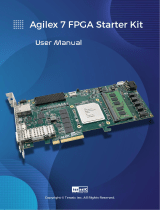
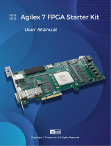
DE10-Agilex
User Manual
2
www.terasic.com
December 8,
2022
Contents
Chapter 1 Overview ................................................................................... 6
1.1 General Description .............................................................................. 6
1.2 Key Features ......................................................................................... 6
1.3. Block Diagram ....................................................................................... 8
1.4. Board Power On .................................................................................... 9
1.5. Board Protection ................................................................................. 12
Chapter 2 Board Component .................................................................. 13
2.1 Board Overview ................................................................................... 13
2.2 Configuration ....................................................................................... 14
2.3 Status and Setup Components ........................................................... 17
2.4 General User Input/Output .................................................................. 23
2.5 Clock Circuit ........................................................................................ 27
2.6 DDR4 SO-DIMM ................................................................................. 31
2.7 QSPF-DD Ports ................................................................................... 54
2.8 PCI Express ........................................................................................ 60
2.9 System Status Interface ...................................................................... 65

DE10-Agilex
User Manual
3
www.terasic.com
December 8,
2022
Chapter 3 System Builder ....................................................................... 68
3.1 Introduction ......................................................................................... 68
3.2 General Design Flow ........................................................................... 69
3.3 Using System Builder .......................................................................... 70
Chapter 4 CFI-Flash Programming ......................................................... 81
4.1 FPGA Configure Operation ................................................................. 83
4.2 CFI Flash Memory Map ....................................................................... 85
4.3 Programming Bit Stream File Into CFI Flash ....................................... 86
4.4 Restore Factory Settings ..................................................................... 90
4.5 Flash_Factory Example ...................................................................... 91
4.6 Flash_User Example ........................................................................... 93
Chapter 5 Peripheral Reference Design ................................................. 94
5.1 Configure Si5397A in RTL ................................................................... 94
5.2 Clock_Controller demo for Si5397 .................................................... 105
5.3 Nios II control for SI5397/ Temperature/ Power/Fan ......................... 107
5.4 Board Information IP ......................................................................... 112
Chapter 6 Memory Reference Design .................................................. 117
6.1 DDR4 SDRAM Test ........................................................................... 117

DE10-Agilex
User Manual
4
www.terasic.com
December 8,
2022
6.2 DDR4 SDRAM Test by Nios II ........................................................... 119
Chapter 7 PCI Express Reference Design for Windows ..................... 125
7.1 PCI Express System Infrastructure ................................................... 125
7.2 PC PCI Express Software SDK ......................................................... 126
7.3 PCI Express Software Stack ............................................................. 127
7.4 PCI Express Library API .................................................................... 134
7.5 PCIe Reference Design - Fundamental ............................................ 139
7.6 PCIe Reference Design - DDR4 ........................................................ 148
Chapter 8 PCI Express Reference Design for Linux ........................... 160
8.1 PCI Express System Infrastructure ................................................... 160
8.2 PC PCI Express Software SDK ......................................................... 161
8.3 PCI Express Software Stack ............................................................. 162
8.4 PCI Express Library API .................................................................... 164
8.5 PCIe Reference Design - Fundamental ............................................ 164
8.6 PCIe Reference Design - DDR4 ........................................................ 171
Chapter 9 Transceiver Verification ....................................................... 181
9.1 Transceiver Test Code ...................................................................... 181
9.2 Loopback Fixture ............................................................................... 181

DE10-Agilex
User Manual
5
www.terasic.com
December 8,
2022
9.3 Testing by Transceiver Test Code ..................................................... 182
9.4 100G Ethernet Example (E-Tile FPGA) ............................................. 185
Chapter 10 Dashboard GUI .................................................................. 192
10.1 Driver Installed on Host ..................................................................... 193
10.2 Run Dashboard GUI .......................................................................... 195
Chapter 11 Additional Information ...................................................... 207
11.1 Getting Help ...................................................................................... 207

DE10-Agilex
User Manual
6
www.terasic.com
December 8,
2022
Chapter 1
Overview
his chapter provides an overview of the DE10-Agilex Development Board and
installation guide.
1.1 General Description
Targeting the compute and acceleration needs from the edge to the core to the cloud,
Terasic’s DE10-Agilex accelerator is purpose-designed to meet the ever-increasing
demands for acceleration, compute, and fast data movement.
The DE10-Agilex is based on the powerful Intel® Agilex™ FPGA to obtain speed and
power breakthrough, with 40% higher performance, 40% lower power for equivalent
performance. The accelerator includes PCI Express Gen 4.0 x16, two 200G
QSFP-DD connectors and offers 32GB of DDR4 up to 680Gbps bandwidth to provide
adaptable acceleration, maximum throughput and highly customizable processing of
data for compute intensive applications.
The DE10-Agilex fully supports Intel® Open VINO™ toolkit, OpenCL™ BSP and
Intel® oneAPI Toolkits to provide optimal Computer Vision and Deep Learning
solutions. Our clients' systems can achieve highest computing performance and
lowest cost for their Data Center and AI applications by leveraging the Agilex® FPGA
on DE10-Agilex accelerator.
1.2 Key Features
The following hardware is implemented on the DE10-Agilex board:
T

DE10-Agilex
User Manual
7
www.terasic.com
December 8,
2022
Intel® Agilex™ F-Series
AGFB014R24B2E2V or AGFB014R24B1E1V (Rev.C board)
1,437K logic elements (LEs)
139 Mbits embedded memory(M20K)
9,020 18-bit x 19-bit multipliers
4,510 Variable-precision DSP blocks
1x PCIe Gen4 x16 Hard IP blocks
Transceivers
16 x 28 Gbps NRZ transceivers (E-tile)
8 of them can run 58 Gbps PAM4
16 x 17.4 Gbps NRZ transceivers (P-tile)
JTAG Header and FPGA Configuration
On-board USB Blaster II or JTAG header for use with the Quartus
Prime Programmer
MAX10 FPGA 10M04SCU169 System Controller and Avalon-ST x16 for
configuration
AS x4 configuration via EPCQ-L configuration device (DNI)
Memory devices
4 DDR4 SO-DIMM sockets, each supports up to 16GB ECC DDR4 SDRAM
128MB Flash(Connected to the System MAX10 FPGA)
General user I/O
4 user controllable LEDs
2 user push buttons
2 user dip switches
Clock interface
50MHz and 100Mhz Oscillators
Programming PLL providing clock for QSFP-DD interface
Dual clocks oscillators for DDR4 SDRAM SO-DIMM
U.FL connector for external clock input
One 2x5 GPIO timing expansion header

DE10-Agilex
User Manual
8
www.terasic.com
December 8,
2022
Communication Ports
Two QSFP-DD Cages
Each can run up to 200Gbps
Compatible with QSFP and QSFP28
PCI Express x16 edge connector
Support for PCIe x16 Gen4
Edge connector for PC motherboard with x16 PCI Express slot
4-Pin UART to USB (Integrated with USB-Blaster with USB Hub)
System Monitor and Control
Dashboard System for System Management (Implement by System
MAX10 FPGA)
Temperature sensor
Fan control
Power monitor
Power Source
PCI Express 8-pin DC 12V power
PCI Express edge connector power
Mechanical Specification
PCI Express full-height and 3/4-length
1.3. Block Diagram
Figure 1-1 shows the block diagram of the DE10-Agilex board. To provide maximum
flexibility for the users, all key components are connected to the Agilex™ FPGA
device. Thus, users can configure the FPGA to implement any system design.

DE10-Agilex
User Manual
9
www.terasic.com
December 8,
2022
Figure 1-1 Block diagram of the DE10-Agilex board
1.4. Board Power On
The DE10-Agilex board can be used in stand-alone or be installed to the Host through
PCIe slot. This section will introduce how to power on the board and the information
that user should notice in these two modes.
Stand-alone Mode
When the DE10-Agilex board is used in stand-alone mode, users can use the 12V
ATX power provided in the kit to connect to the 8-pin 12V ATX power connector (See
Figure 1-2) of the DE10-Agilex board. To power up the board, user need to turn the
power switch SW2 to “ON” position.

DE10-Agilex
User Manual
10
www.terasic.com
December 8,
2022
Figure 1-2 Board Power Control Switch
Install to Host
When the DE10-Agilex is installed on the Host via PCIe slot. Although the Host can
provide power to DE10-Agilex board via PCIe slot, but Terasic strongly recommends
that users connect an external power (through the 2x4 ATX power connector) to the
board. This can prevent the power provided from Host unable to meet the power
requirement of DE10-Agilex. If the power supply to the board is insufficient, it may
cause some components to be abnormal.
In order to avoid insufficient power supply to the board, there is a force external power
switch (SW1) on the board (See Figure 1-4). The SW1 is default set as ON. When
install the board on the PCIe slot in the PC, users must connect the 2x4 pin 12V DC
external power connector to the board, otherwise the board will not be power on. This
restriction is designed to avoid FPGA damage due to insufficient power. Users can set
it as OFF if the FPGA utilization rate is low and PCIe edge power source is sufficient.


DE10-Agilex
User Manual
12
www.terasic.com
December 8,
2022
1.5. Board Protection
The temperature of DE10-Agilex board will have a lot to do with the user's design
code, chassis, and ambient temperature. When using DE10-Agilex board in the server.
Customers should pay attention to whether the temperature of DE10-Agilex board is
too high to avoid abnormal work for user’s design or even damage to the board.
The Dashbaord_gui software (see chapter 10 of this user manual) is provided in the
system CD to allow users to monitor the temperature status of the board. A
temperature monitor IP (see section 5.4 in the user manual) is also provided so that
the user can directly monitor the temperature status in the Agilex FPGA.
If the board temperature is too high, it is recommended that customers can switch the
PCIe slot position in the server chassis or increasing the fan strength in the chassis,
or replace the chassis to a big space, or reduce the ambient temperature to improve
cooling system.
In addition, the efficiency of the DE10-Agilex cooling system will decrease with the
aging of dust and fans, so customers should re-evaluate the cooling efficiency
regularly.

DE10-Agilex
User Manual
13
www.terasic.com
December 8,
2022
Chapter 2
Board Component
his chapter introduces all the important components on the DE10-Agilex.
2.1 Board Overview
Figure 2-1 and Figure 2-2 is the top and bottom view of the DE10-Agilex development
board. It depicts the layout of the board and indicates the location of the connectors
and key components. Users can refer to this figure for relative location of the
connectors and key components.
Figure 2-1 FPGA Board (Top)
T

DE10-Agilex
User Manual
14
www.terasic.com
December 8,
2022
Figure 2-2 FPGA Board (Bottom)
2.2 Configuration
The FPGA board supports the following configuration methods for the Intel® Agilex™
FPGA:
Avalon-ST x16
JTAG
Active Serial (AS) normal and fast modes (Need to Install Flash by user)
To switch these methods on the DE10-Agilex board, the user needs to switch the
MSEL[2:0] pin of FPGA on SW6 and SW7 to change the configuration methods (See
Figure 2-3 ). For details, please refer to Setup Configure Mode part of the section
2.3.

DE10-Agilex
User Manual
15
www.terasic.com
December 8,
2022
Figure 2-3 MSEL switch of the board
Detailed descriptions for each configuration methods are list in below.
Avalon-ST x16
Avalon-ST is the fastest configuration scheme for Intel® Agilex™ devices. When using
this mode, while power up the DE10-Agilex board, the System MAX10 FPGA on the
board (used as an external host) will read the configuration file in the Flash, and then
programming the data into the FPGA through the Avalon-ST protocol.
On DE10-Agilex board, the data bus width of Avalon-ST mode is 16-bit (Avalon-ST x
16 mode). To set DE10-Agilex board to Avalon-ST mode, users need to set MSEL[2:0]
to "101" (See Setup Configure Mode part of the section 2.3). For how to program the
configuration file into the Flash, please refer to chapter 4.

DE10-Agilex
User Manual
16
www.terasic.com
December 8,
2022
Figure 2-4 Block diagram of the Avalon-ST x 16 mode on the board
JTAG
JTAG-chain device programming is one of the most common and general methods.
JTAG-chain device configuration uses the JTAG pins to configure the Intel® Agilex™
FPGA directly with the .sof file. Use this mode to configure FPGA, users do not need to
modify MSEL specifically [2:0] pin, JTAG-chain device programming can be used
under any setting. On DE10-Agilex board, users can use JTAG-chain device
programming through the onboard USB blaster II circuit.
For JTAG programming by on-board USB-Blaster II, the following procedures show
how to download a configuration bit stream into the Agilex FPGA:
Make sure that power is provided to the FPGA board
Connect your PC to the FPGA board using a Mini-USB cable and make sure
the USB-Blaster II driver is installed on PC.
Launch Quartus Prime programmer and make sure the USB-Blaster II is
detected.
In Quartus Prime Programmer, add the configuration bit stream file (.sof),
check the associated “Program/Configure” item, and click “Start” to start
FPGA programming.
Active Serial (AS)
A serial flash (QSPI interface) is used on the D10-Agilex board for AS mode boot.
When the Agilex FPGA is running in AS mode, the SDM (Secure device manager)
block in the FPGA will actively go to the serial flash to read the stored configuration file
to boot the FPGA. To use AS mode, the MSEL[2:0] pins must be set to “001” (See

DE10-Agilex
User Manual
17
www.terasic.com
December 8,
2022
Setup Configure Mode part of the section 2.3 for detailed).User can the use Intel
Quartus Prime Programmer tool to program the serial flash device through JTAG
interface. The SDM in the FPGA will emulate AS programming. The manufacturer and
part number of the serial flash are Micron and MT25QU128ABA8E12-0SIT.
.
Figure 2-5 Block diagram of the Active serial mode on the board
2.3 Status and Setup Components
Status LED
The FPGA Board development board includes board-specific status LEDs to indicate
board status. Please refer to Figure 2-6 and Table 2-1 for the description of the LED
indicator.

DE10-Agilex
User Manual
18
www.terasic.com
December 8,
2022
Figure 2-6 Position of the status LED
Table 2-1 Status LED
Board
Reference
LED Name
Description
D14
12-V Power
Illuminates when 12-V power is active.
D13
3.3-V Power
Illuminates when 3.3-V power is active.
D11
FAN_ALERT_n
Illuminates when the fan is abnormal, such
as when the fan speed is different from
expected
D7
MAX_CONF_DONE
Illuminates when the FPGA is successfully
configured.
D6
MAX_LOAD
Illuminates when the MAX 10 FPGA System
Controller is actively configuring the FPGA.
D5
MAX_ERROR
Illuminates when the MAX 10 FPGA System
Controller fails to configure the FPGA.
D4
BOOT_PAGE
Illuminates when FPGA is configured by the

DE10-Agilex
User Manual
19
www.terasic.com
December 8,
2022
factory configuration bit stream.
D3
FPGA_SD_LED
Illuminates when the FPGA temperature or
the board temperature exceeds 95 degrees
or the power consumption exceeds 180W.
Also, all the power of the FPGA will be cut
off. (*1)
D2
POWER_LEDG
Illuminates when the 3.3V power good and
power sequence process finished. (*1)
D1
POWER_LEDR
Illuminates when the 3.3V power abnormal
or power sequence process failed. (*1)
D16
JTAG_RX
Illuminates when the USB Blaster II circuit is
transmitting data
D17
JTAG_TX
Illuminates when the USB Blaster II circuit is
receiving data
(*1) : This LED will light up for about 0.3 second
when the board is powered up
then turn off.
Setup PCI Express Control DIP switch
The PCI Express Control DIP switch (SW8) is provided to enable or disable different
configurations of the PCIe Connector. Table 2-2 lists the switch controls and
description.
Figure 2-7 Position of the PCIe mode switch

DE10-Agilex
User Manual
20
www.terasic.com
December 8,
2022
Table 2-2 SW8 PCIe Control DIP Switch
Board
Reference
Signal Name
Description
Default
SW8.1
PCIE_PRSNT2n_x1
On : Enable x1 presence detect
Off: Disable x1 presence detect
Off
SW8.2
PCIE_PRSNT2n_x4
On : Enable x4 presence detect
Off: Disable x4 presence detect
Off
SW8.3
PCIE_PRSNT2n_x8
On : Enable x8 presence detect
Off: Disable x8 presence detect
Off
SW8.4
PCIE_PRSNT2n_x16
On : Enable x16 presence detect
Off: Disable x16 presence detect
On
Setup Configure Mode
The SW7 and SW6 slide switches are used to specify the configuration mode of the
FPGA. As currently only Avalon-ST x16 mode is supported (QSPI flash is not soldered
on the board), please set MSEL[2:0] to 101 positions as shown in Figure 2-8 and
Figure 2-9.
Figure 2-8 Position of slide switches SW6 and SW7 for Configuration Mode
/