TABLE OF CONTENTS
SERVICE UPDATES ....................................................................................... 4
SERVICE UPDATES - SG .............................................................................. 4
GENERAL .................................................................................................. 5
INTRODUCTION ....................................................................................... 5
INSTALLATION ........................................................................................ 5
OPERATION ........................................................................................... 5
CLEANING ............................................................................................. 5
LUBRICATION ......................................................................................... 5
SPECIFICATIONS ...................................................................................... 5
TOOLS ................................................................................................. 5
REMOVAL AND REPLACEMENT OF PARTS ............................................................... 6
COVERS AND PANELS ................................................................................ 6
TOP FRONT COVER ............................................................................... 6
BOTTOM FRONT COVER .......................................................................... 6
CONTROL PANEL ................................................................................. 6
RIGHT SIDE PANEL ................................................................................ 6
CONTROL PANEL COMPONENTS ..................................................................... 7
COMPONENT PANEL COMPONENTS ................................................................. 7
TEMPERATURE PROBE ............................................................................... 8
GAS BURNER ......................................................................................... 9
GAS ORIFICE .......................................................................................... 9
GAS SOLENOID VALVE .............................................................................. 10
IGNITION CONTROL MODULE ....................................................................... 11
SPARK IGNITER AND FLAME SENSE ................................................................ 12
BLOWER AND MOTOR ENDING AT PRODUCTION DATE OF 3/18/2018 .............................. 13
BLOWER AND MOTOR STARTING AT PRODUCTION DATE OF 3/19/2018 ........................... 15
OVEN DOORS AND BEARINGS (INDEPENDENT DOORS) ENDING AT
PRODUCTION DATE OF 1/21/2018 ............................................................... 16
OVEN DOORS (INDEPENDENT DOORS) STARTING AT PRODUCTION DATE OF 1/22/2018 ......... 17
ROLLER LATCH ASSEMBLY (INDEPENDENT DOORS) ............................................... 18
DOOR WINDOW ...................................................................................... 18
DOOR SWITCH ....................................................................................... 19
HIGH LIMIT THERMOSTAT ........................................................................... 19
INTERIOR LIGHTS .................................................................................... 20
COOLING FAN ........................................................................................ 20
INTERIOR LIGHTS (REAR MOUNTED, ROUND) ...................................................... 21
INTERIOR LIGHTS (SIDE MOUNTED, SQUARE) ...................................................... 21
DOOR ADJUSTMENT ................................................................................. 23
SERVICE PRODCEDURES AND ADJUSTMENTS ......................................................... 25
SOLID STATE TEMPERATURE CONTROL CALIBRATION ............................................ 25
SOLID STATE TEMPERATURE CONTROL TEST ..................................................... 26
TEMPERATURE PROBE TEST ....................................................................... 27
GAS VALVE PRESSURE CHECK ..................................................................... 27
VERIFICATION OF SPARK AT IGNITOR .............................................................. 28
DOOR SWITCH ADJUSTMENT ....................................................................... 29
BLOWER ADJUSTMENT .............................................................................. 29
DOOR ADJUSTMENT ................................................................................. 30
DOOR STRIKE ADJUSTMENT (INDEPENDENT DOORS) ............................................. 31
FLAME SENSE CURRENT TEST ...................................................................... 31
ELECTRICAL OPERATION ................................................................................ 34
COMPONENT LOCATION ............................................................................. 34
COMPONENT FUNCTION ............................................................................ 37
SEQUENCE OF OPERATION ......................................................................... 38
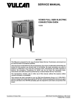
SG SERIES GAS CONVECTION OVENS
F45525 Rev. B (1118) Page 2 of 46