Page is loading ...

INSULATED HUMIDIFIED
HOLDING & PROOFING CABINET
VHU18
- NOTICE -
This Manual is prepared for the use of trained Vulcan Service
Technicians and should not be used by those not properly
qualified.
This manual is not intended to be all encompassing. If you have
not attended a Vulcan Service School for this product, you should
read, in its entirety, the repair procedure you wish to perform to
determine if you have the necessary tools, instruments and skills
required to perform the procedure. Procedures for which you do
not have the necessary tools, instruments and skills should be
performed by a trained Vulcan Service Technician.
The reproduction, transfer, sale or other use of this Manual,
without the express written consent of Vulcan, is prohibited.
This manual has been provided to you by ITW Food Equipment
Group LLC ("ITW FEG") without charge and remains the property
of ITW FEG, and by accepting this manual you agree that you will
return it to ITW FEG promptly upon its request for such return at
any time in the future.
SERVICE MANUAL
A product of Vulcan-Hart 3600 North Point Blvd Baltimore, MD 21222
F45642 Rev. A (0518)

TABLE OF CONTENTS
SERVICE UPDATES ....................................................................................... 3
SERVICE UPDATES ................................................................................... 3
GENERAL .................................................................................................. 4
INTRODUCTION ....................................................................................... 4
INSTALLATION, OPERATION AND CLEANING ......................................................... 4
TOOLS ................................................................................................. 4
SPECIFICATIONS ...................................................................................... 4
SERVICE PROCEDURES AND ADJUSTMENTS ............................................................ 5
TEMPERATURE AND HUMIDITY CALIBRATION ....................................................... 5
RESET SENSOR CODES .............................................................................. 5
HEATER ELEMENT TEST .............................................................................. 6
REMOVAL AND REPLACEMENT OF PARTS ............................................................... 7
TOP COVER ........................................................................................... 7
FOOD COMPARTMENT FAN ........................................................................... 7
HEATING ELEMENT ................................................................................... 7
CONTROLLER BOARD - TEMPERATURE & HUMIDITY ................................................ 9
SENSOR BOARD - TEMPERATURE & HUMIDITY ..................................................... 10
DOOR ASSEMBLY .................................................................................... 11
DOOR GASKET ....................................................................................... 12
DOOR LATCH (MAGNETIC) ........................................................................... 12
FUSE ................................................................................................. 12
FUSE HOLDER ....................................................................................... 13
ELECTRICAL OPERATION ................................................................................ 14
COMPONENT LOCATIONS ........................................................................... 14
COMPONENT DESCRIPTIONS ....................................................................... 15
WIRING DIAGRAM .................................................................................... 16
SEQUENCE OF OPERATION ......................................................................... 16
TROUBLESHOOTING ..................................................................................... 17
TROUBLESHOOTING ................................................................................. 17
ERROR CODES ...................................................................................... 17
INSULATED HUMIDIFIED HOLDING & PROOFING CABINET
© VULCAN 2018
F45642 Rev. A (0518) Page 2 of 17


GENERAL
INTRODUCTION
This manual is applicable only to models listed on the
cover page. Procedures in this manual will apply to all
models unless specified. Pictures and illustrations can
be of any model unless they need to be model specific.
INSTALLATION, OPERATION AND
CLEANING
For detailed installation, operation and cleaning
instructions, refer to the Installation & Operation
Manual sent with each unit. The manual is also
available online at www.vulcanequipment.com.
TOOLS
Standard
1. Standard set of hand tools.
2. VOM with minimum of NFPA-70E CATIII 600V,
UL/CSA/TUV listed. Sensitivity of at least 20,000
ohms per volt. Meter leads must also be rated at
CAT III 600V.
3. Clamp on type amp meter with minimum of
NFPA-70E CAT III 600V,UL/CSA/TUV listed.
4. Temperature tester (thermocouple type).
5. ESD (Electrostatic discharge) Protection Kit.
Special
• Handheld, digital temperature and humidity
sensor Grainger No. 3LYH7 or equivalent.
SPECIFICATIONS
Electrical
Model Volts Wattage Amperage
VHU18 120 1,500 12.5
Heating Elements
Model Wattage Voltage Resistance
VHU18 1500
(Standard) 120 8.80-10.27
Pan Capacity
Model
Capacity *
12" X 20" X 2 ½" 18" X 26"
SHEET PANS
VHU18 36 18
(*) Capacity based on 3" spacing between pans.
INSULATED HUMIDIFIED HOLDING & PROOFING CABINET - GENERAL
F45642 Rev. A (0518) Page 4 of 17

SERVICE PROCEDURES AND ADJUSTMENTS
TEMPERATURE AND HUMIDITY
CALIBRATION
The warmer and its parts are hot. Use care when
operating, cleaning or servicing the oven.
1. Check room temperature.
2. Place temperature and humidity probe at the
center of the cabinet.
3. Set unit temperature to 145°F.
4. Set relative humidity to 65%RH.
5. Wait 45 minutes.
6. The temperature setting should be between 138
- 152F° and relative humidity between 45%RH -
85%RH.
If temperature setting numbers do not match,
check the following...
A. Check continuity to both Humidity and Air
heating elements.
B. Make sure VHU Interior Pan has black
coating on the bottom.
VERIFY
• When using cabinet, frequently opening the
door will affect average internal
temperature. Modify set temperature and
humidity as necessary to ensure product is
held above appropriate food safe
temperature.
RESET SENSOR CODES
The warmer and its parts are hot. Use care when
operating, cleaning or servicing the oven.
1. Reset unit (turn it off, then on).
2. Turn unit off and remove sensor cover.
NOTE: Sensor board is located within the food cavity,
behind the control board, under a sheet metal cover.
Fig. 1
3. Dry off sensor and wires.
Fig. 2
4. Disconnect sensor wire harness plugs and dry
out any moisture in connectors.
5. Plug sensor wire connectors into board.
6. Turn unit on to verify error code has cleared.
7. If error codes are not clear, replace both
SENSOR BOARD AND WIRE HARNESS.
8. Install sensor board cover.
9. Verify operation.
INSULATED HUMIDIFIED HOLDING & PROOFING CABINET - SERVICE PROCEDURES AND ADJUSTMENTS
Page 5 of 17 F45642 Rev. A (0518)

HEATER ELEMENT TEST
Certain procedures in this section
require electrical test or
measurements while power is
applied to the machine. Exercise
extreme caution at all times and
follow Arc Flash procedures. If test
points are not easily accessible,
disconnect power and follow
Lockout/Tagout procedures, attach
test equipment and reapply power to
test.
1. Access the heater element being tested.
• HUMIDITY ELEMENT (VHU INTERIOR
PAN)
• AIR ELEMENT
2. Check resistance using HEATING ELEMENT
table.
Heating Elements
Model Wattage Voltage Resistance
VHU18 1500 120 8.80-10.27
NOTE: If noumbers do not match, replace HEATING
ELEMENT.
INSULATED HUMIDIFIED HOLDING & PROOFING CABINET - SERVICE PROCEDURES AND ADJUSTMENTS
F45642 Rev. A (0518) Page 6 of 17

REMOVAL AND REPLACEMENT OF PARTS
TOP COVER
Disconnect the electrical power to
the machine and follow lockout /
tagout procedures.
1. Remove eight screws securing top cover to
cabinet.
NOTE: Fig. 3 Shown without top vent fan (First
Generation Production). Fig. 4 Shown with top cooling
fan (Second Generation Production).
Fig. 3
Fig. 4
2. Unplug fan cord, if applicable.
3. Lift top cover off cabinet.
4. Reverse procedure to install.
FOOD COMPARTMENT FAN
Disconnect the electrical power to
the machine and follow lockout /
tagout procedures.
1. Remove upper pans and pan supports for
clearance to access food compartment fan.
2. Loosen fan mounting screws.
Fig. 5
3. Slide fan (1, Fig. 5) to access power connector.
4. Disconnect power connector.
5. Reverse procedure to install and check for proper
operation.
HEATING ELEMENT
Disconnect the electrical power to
the machine and follow lockout /
tagout procedures.
Humidity Element (VHU Interior Pan)
1. Remove pans and universal tray slides.
2. Remove VHU interior pan.
3. Remove screw securing heating element
mounting clip to bottom of cabinet.
INSULATED HUMIDIFIED HOLDING & PROOFING CABINET - REMOVAL AND REPLACEMENT OF PARTS
Page 7 of 17 F45642 Rev. A (0518)

Fig. 6
4. Remove two screws securing element.
Fig. 7
5. Pull element out.
6. Disconnect heating element wires.
Fig. 8
7. Reverse procedure to install and check for proper
operation.
Air Element
1. Remove pans and universal tray slides.
2. Loosen rail guide support screws.
3. Remove rail guides.
Fig. 9
4. Remove bottom screws from side panel.
INSULATED HUMIDIFIED HOLDING & PROOFING CABINET - REMOVAL AND REPLACEMENT OF PARTS
F45642 Rev. A (0518) Page 8 of 17

Fig. 10
5. Remove bottom cover screws.
Fig. 11
6. Carefully clear element while lifting cover from
right side.
Fig. 12
7. Remove two screws securing element.
Fig. 13
8. Pull element out.
9. Disconnect heating element wires.
Fig. 14
10. Reverse procedure to install and check for proper
operation.
CONTROLLER BOARD -
TEMPERATURE & HUMIDITY
Disconnect the electrical power to
the machine and follow lockout /
tagout procedures.
1. Remove temperature and humidity control
knobs.
2. Remove two nuts on front of board.
3. Remove TOP COVER.
4. Lift insulation and fold back toward rear of
cabinet.
5. Remove controller board mounting nuts.
INSULATED HUMIDIFIED HOLDING & PROOFING CABINET - REMOVAL AND REPLACEMENT OF PARTS
Page 9 of 17 F45642 Rev. A (0518)

Fig. 15
6. Lift controller board to access wire connections.
7. Note wire locations and disconnect from
controller board.
8. Reverse procedure to install and check for proper
operation.
SENSOR BOARD - TEMPERATURE
& HUMIDITY
Disconnect the electrical power to
the machine and follow lockout /
tagout procedures.
NOTE: Sensor board is located within the food cavity,
behind the control board, under a sheet metal cover.
Sensor Board
1. Disconnect power supply.
2. Remove sensor board cover.
Fig. 16
3. Disconnect sensor wire plugs.
Fig. 17
4. Remove double-sided tape from cabinet surface.
5. Clean cabinet surface.
6. Apply double-sided tape to sensor and mount.
7. Plug sensor wire connectors into board.
8. Verify proper operation.
Sensor Board Wire Harness
1. Remove sensor board cover.
Fig. 18
2. Disconnect sensor wire plugs.
Fig. 19
3. Remove TOP COVER.
4. Disconnect wire harness plugs from board.
INSULATED HUMIDIFIED HOLDING & PROOFING CABINET - REMOVAL AND REPLACEMENT OF PARTS
F45642 Rev. A (0518) Page 10 of 17

Fig. 20
5. Release grommets from top panel.
Fig. 21
6. Pull wire harness out.
7. Reverse steps to install.
Position grommets correctly during installation so they
retain moisture from escaping.
8. Verify proper operation.
DOOR ASSEMBLY
1. Remove door hinge covers (1, Fig. 22) from lower
and upper door hinge.
Fig. 22
Remain in control of door when removing hinges.
2. Remove door hinge inside mounting screws
from lower door hinge first.
Fig. 23
3. Remove door hinge inside mounting screws from
upper door hinge while supporting door weight.
4. Lift door assembly from cabinet.
5. Reverse procedure to install.
6. Check for proper operation.
INSULATED HUMIDIFIED HOLDING & PROOFING CABINET - REMOVAL AND REPLACEMENT OF PARTS
Page 11 of 17 F45642 Rev. A (0518)

DOOR GASKET
1. Open door to access gasket.
2. Remove door gasket by pulling it out from
retaining channel in door assembly.
Fig. 24
3. Install gasket in each corner on door assembly.
A. Press gasket retaining lip into channel on
door assembly.
B. Work gasket into channel about four inches
away from corner, in each direction.
Fig. 25
4. Starting at the top, press gasket retaining lip into
channel on door assembly while moving toward
middle.
5. Repeat each side to complete gasket installation.
6. Check door for proper operation.
DOOR LATCH (MAGNETIC)
1. Open door.
2. Remove screws securing door latch to door
assembly.
Fig. 26
3. Reverse procedure to install.
4. Check for proper operation.
FUSE
Disconnect the electrical power to
the machine and follow lockout /
tagout procedures.
1. Unscrew fuse cover from back panel.
INSULATED HUMIDIFIED HOLDING & PROOFING CABINET - REMOVAL AND REPLACEMENT OF PARTS
F45642 Rev. A (0518) Page 12 of 17

2. Replace with same size and type of fuse.
3. Install cover.
FUSE HOLDER
Disconnect the electrical power to
the machine and follow lockout /
tagout procedures.
1. Remove TOP COVER.
2. Note fuse wiring and disconnect.
Fig. 28
3. Remove fuse holder mounting screws on back
panel.
Fig. 29
4. Reverse procedure to install and verify proper
operation.
INSULATED HUMIDIFIED HOLDING & PROOFING CABINET - REMOVAL AND REPLACEMENT OF PARTS
Page 13 of 17 F45642 Rev. A (0518)

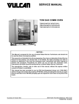
ELECTRICAL OPERATION
COMPONENT LOCATIONS
Fig. 30
INSULATED HUMIDIFIED HOLDING & PROOFING CABINET - ELECTRICAL OPERATION
F45642 Rev. A (0518) Page 14 of 17

Item Description
1 Temperature & humidity Controller (behind control panel)
2 Temperature Display and Control Knob
3 Humidity Display and Control Knob
4 Food Compartment Fan
5 Heating element air (below bottom cover)
6 Heating element humidity (VHU interior pan)
7
VHU Interior Pan: Special Stainless Steel Pan with High
temp black coating on bottom; gets placed in opening
above heating element
8VHU Exterior Pan: Standard Stainless Steel Pan located
under unit for water collection
9 Cooling Fan
COMPONENT DESCRIPTIONS
ITEM DESCRIPTION
Fuse Protects controller board and electrical components.
Power Switch Provides power to the control circuit. Internal red light indicates ON (SPST).
Food Compartment Fan Circulates air inside the cabinet. Moisture resistant with metal fan blades.
Sensor Board Senses temperature and humidity inside the cabinet and transmits signal to
controller board.
Controller Board Controls the temperature, humidity and fan inside the cabinet.
Heating Element - VHU
Interior Pan Heats the water to provide humidity.
Heating Element - Dry Heats the air to keep prepared food at the proper serving temperatures.
Vent Fan Circulates air in the electrical component area.
INSULATED HUMIDIFIED HOLDING & PROOFING CABINET - ELECTRICAL OPERATION
Page 15 of 17 F45642 Rev. A (0518)

WIRING DIAGRAM
Fig. 31
SEQUENCE OF OPERATION
1. Conditions.
A. Unit connected to correct voltage and is
properly grounded.
B. Power switch is off.
2. Power switch turned on.
A. Relays K1, K2 and K3 are de-energized
(contacts N.O.).
B. Controller board performs diagnostic test
and verifies temperature and humidity input
signals are present.
C. If no errors codes display, the temperature
and humidity settings flash in each display
window.
3. Fan relay K2 is energized, K2 contacts close and
power the fans.
4. Based on temperature and humidity settings, the
board determines whether K1 relay will be
energized to power element 1 (dry air); or K3
relay will be energized to power element 2 (humid
air).
NOTE: When temperature or humidity settings are
changed, after a brief pause, both element relays (K1
& K3) will be de-energized and return to N.O. position.
Heating and humidity generation stop. The relay
numbers will flash in each display window. Based on
temperature and humidity level in cabinet vs. setting,
the controller board determines which relay to
energize. The number of the energized relay will flash
in display window.
5. Adjust temperature and humidity to desired
levels.
6. Turn power switch off stops heating cycle.
INSULATED HUMIDIFIED HOLDING & PROOFING CABINET - ELECTRICAL OPERATION
F45642 Rev. A (0518) Page 16 of 17

TROUBLESHOOTING
TROUBLESHOOTING
Symptom Possible Cause
Cabinet not operating. 1. Cabinet not connected to power source or circuit breaker tripped.
2. Cabinet lighted power switch not ON or malfunctioning.
Ground Fault Circuit Indicator (GFCI)
tripped.
1. Shorted heating element.
2. Pinched/damaged wiring (heating elements or fan).
3. Damaged power cord.
Cabinet connected to power, switch is
ON, circuit breaker is ON but cabinet not
heating.
1. Heating element malfunction.
2. Temperature controller malfunction.
Cabinet not heating properly.
1. Black coated water pan should be used inside unit.
2. Element wires disconnected from element. Replace wire assembly
and element.
3. Fan not circulating air or malfunction.
4. Door not sealing properly.
5. Temperature controller needs calibrating or malfunction.
Fan not operating
1. Temperature controller not supplying power to fan (malfunction).
2. Fan wiring not connected or malfunction.
3. Fan not circulating air or malfunction.
Error codes, E01, E02, or E03. 1. Refer to:RESET SENSOR CODES.
Moisture present at the top of the cabinet
near the control board.
1. Fan mounted to top cover blocked off.
2. Fan mounted to top cover not functioning.
3. Fan mounted to top cover missing.
Corrosion present inside cabinet.
1. Periodic cleaning needed. Refer to Operations manual.
2. Hardware has rusted. Replace rusted hardware with 18-8 stainless
steel components and replace food cavity fan.
ERROR CODES
Code Description Correction
E01 Displays when controller detects and
open temperature sensor
Refer to: RESET SENSOR CODESE02 Displays when controller detects a
shorted temperature sensor.
E03 RH Display is ON and there is a short
10 RH error.
INSULATED HUMIDIFIED HOLDING & PROOFING CABINET - TROUBLESHOOTING
Page 17 of 17 F45642 Rev. A (0518)
/