Page is loading ...

STEELCRAFT EXTREME HEAVY DUTY GRILLE GUARD
2021-24 FORD BRONCO
Page 1 of 8 11/8/22 (DP)
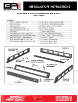
PARTS LIST:
1
Heavy Duty Grill Guard
4
12-1.75mm Nylon Lock Nuts
1
Driver/Left Side Mounting Bracket
4
8-1.25mm x 30mm Button Head Bolts
1
Passenger/Right Side Mounting Bracket
4
8-1.25mm x 25mm Hex Bolts
4
Bracket Spacers (use with steel bumper only)
12
8mm x 24mm x 2mm Flat Washers
4
Double Sided Adhesive Foam (for spacers)
4
8mm Lock Washers
1
Driver/left Top Support Bracket (plastic bumper)
4
8mm Nylon Lock Nuts
1
Passenger/Right Top Support Bracket (plastic bumper)
2
6-1.00mm x 20mm Hex Bolts
1
Driver/left Top Support Bracket (steel bumper)
2
6mm x 18mm x 1.5mm Flat Washers
1
Passenger/Right Top Support Bracket (steel bumper)
2
6mm Lock Washers
1
Driver/left Mid Support Bracket (steel bumper)
2
6mm Flange Nuts
1
Passenger/Right Mid Support Bracket (steel bumper)
1
5mm Wrench
4
12-1.75mm x 35mm Hex Bolts
1
4mm Wrench
8
12mm x 32mm x 3mm Flat Washers
PROCEDURE:
REMOVE CONTENTS FROM BOX AND VERIFY ALL PARTS ARE PRESENT. READ INSTRUCTIONS
CAREFULLY. ASSISTANCE IS RECOMMENDED. INSTALLATION WILL INTERFERE WITH FRONT
BUMPER MOUNTED SENSORS. SENSOR RELOCATION KIT REQUIRED FOR PARKING SENSOR
OPERATION-NOT INCLUDED. CUTTING IS REQUIRED.
Passenger/right Mid
Support Bracket
(steel bumper only)
Driver/left
Mounting Bracket
(4) Bracket Spacers (steel
bumper only)
Passenger/right Long
Support Bracket
Passenger/right
Mounting Bracket
Driver/left Mid Support
Bracket (steel bumper
only)
(4) 2-sided Foam Decals
(steel bumper only)
Passenger/right Short
Support Bracket
Driver/left Short
Support Bracket
Driver/left Long
Support Bracket

STEELCRAFT EXTREME HEAVY DUTY GRILLE GUARD
2021-24 FORD BRONCO
Page 2 of 8 11/8/22 (DP)
1. Determine if the vehicle is equipped with a plastic bumper cover or steel “option” bumper.
Models with plastic bumper cover:
a. Remove the plastic covers from the front of the bumper, (Figures 1 & 2). NOTE: Unplug sensors, if
equipped, to remove covers.
b. From the front, remove the (2) inner factory hex bolts attaching the driver/left side of the bumper
assembly to the end of the frame, (Figure 2). NOTE: Only remove the inner bolts, do not remove the
outer bolts.
c. Select the driver/left Frame Mounting Bracket, (Figure 3). Reuse the (2) OE hex bolts to attach the
Frame Bracket to the bumper, (Figure 4).
d. Select the driver/left plastic cover. Measure 4-1/4” in from the inner end of the cover, (Figure 5). Use
masking tape or a marker to draw a vertical line on the inside of the cover. Cut the cover along line.
Check fit of cover to bumper and bracket and trim cover, if necessary, (Figure 6). Do not reinstall
cover at this time.
e. Repeat the previous Steps to attach the passenger/right Frame Bracket and to cut the cover.
Models with optional steel bumper:
a. Remove the hoop from the top of the bumper if equipped, (Figure 7).
b. Remove the covers surrounding the tow hooks, (Figure 8).
c. From the front, remove the (2) inner factory hex bolts attaching the driver/left tow hook to the bumper,
(Figure 9). NOTE: Only remove the inner bolts, do not loosen or remove the outer bolts.
d. Select (2) Steel Spacers and (2) double sided Foam Decals. Use the double sided Foam Decals to
“stick” the Spacers to the inner pockets in the tow hook, (Figure 10).
e. Select the driver/left Frame Mounting Bracket. Reuse the (2) OE hex bolts to attach the driver//left
Frame Bracket to the Spacers and the bumper, (Figures 10 & 11).
f. Select the driver/left plastic cover. Hold cover in position over Bracket. Check fit of cover to bracket
and trim cover as necessary, (Figures 12 & 13). Do not reinstall cover at this time.
g. Repeat the previous Steps to attach the passenger/right Frame Bracket and to cut the cover.
h. Remove the (2) outer bolts from the driver/left side of the bumper, (Figure 14).
i. Select the driver/left Mid Support Bracket, (Figure 15). Attach the Mid Bracket to the bumper with the
included (2) 8mm x 30mm Button Head Bolts, (2) 8mm Lock Washers and (2) 8mm Flat Washers. Do
not fully tighten hardware. Repeat Step to attach the passenger/right Mid Support Bracket.
2. Open the front hood. Remove the plastic cover from the top of the grille and radiator, (Figure 16).
3. Locate the large and small hole in the driver/left side of the radiator core support, (Figure 17). Select the
correct driver/left Top Support Bracket, (Figure 18).
a. Models with plastic bumpers: Use the shorter Top Support Brackets with holes for identification.
b. Models with steel option bumper: Use the longer Top Support Brackets (no ID holes).
4. Insert the Bracket through the opening in the grille, (Figure 19). On models without opening, it will be
necessary to cut an opening in the grille for the Support Bracket. Line up the end of the Bracket with the
smaller mounting hole. Attach the Bracket to the hole in the core support with (1) 6mm x 20mm Hex Bolt,
(1) 6mm Lock Washer, (1) 6mm Flat Washer and (1) 6mm Flange Nut, (Figures 18 & 19). Leave
hardware loose.
5. Repeat Steps 3 & 4 to attach the passenger/right Top Support Bracket.
6. Carefully unwrap the Grille Guard.
7. With assistance, hold the Grille Guard assembly up to the outside of the Frame Brackets. Attach the
driver/left end of the Grille Guard to the Frame Bracket with the included (2) 12mm x 35mm Hex Bolts, (4)
12mm Flat Washers and (2) 12mm Nylon Lock Nuts, (Figures 20 & 21). Repeat this Step to attach the
passenger/right side of the Grille Guard. Do not fully tighten hardware at this time.
a. Models with steel bumper only: Attach the Mid Mount Bracket to the outside of the Grille Guard with
(1) 8mm x 25mm Hex Bolt, (2) 8mm Flat Washers and (1) 8mm Nylon Lock Nut, (Figure 22). Do not
fully tighten hardware. Repeat this Step to attach the passenger/right Mid Support Bracket.
8. Attach the Top Support Brackets to tabs on the back of the Grille Guard with the included (2) 8mm x
25mm Hex Bolts, (4) 8mm Flat Washers and (2) 8mm Nylon Lock Nuts, (Figure 23).
9. Center the Grille Guard to the vehicle and fully tighten all Mounting Bracket and Support Bracket to vehicle
hardware only at this time. Temporarily remove the Grille Guard.

STEELCRAFT EXTREME HEAVY DUTY GRILLE GUARD
2021-24 FORD BRONCO
Page 3 of 8 11/8/22 (DP)
10. Reinstall the plastic bumper covers removed and cut in Step 1. Reattach the plastic cover to the top of the
grille and radiator removed in Step 2.
11. Reinstall the Grille Guard as described int Steps 7 & 8. Adjust the Grille Guard and fully tighten all
hardware.
12. On models with grille mounted cameras, remove the center panel from the Grille Guard, (Figure 24).
13. Do periodic inspections to the installation to make sure that all hardware is secure and tight.
To protect your investment, do not use any type of polish or wax that may contain abrasives that could damage the finish.
Mild soap may be used to clean the Grille Guard.
Driver/left Side Installation Pictured
(Fig 2) Models with plastic bumper cover
(see Fig 1), remove bumper pads from
bumper (driver/left side pictured). Note,
unplug parking sensors if equipped
(Fig 1) Example of OE plastic bumper
(Fig 4) Models with plastic bumper cover
(see Fig 1), reuse the (2) OEM hex bolts to
attach the driver/left Mounting Bracket to
the front of the bumper (arrow)
(Fig 3) Models with plastic bumper cover
(see Fig 1), reuse the (2) OEM hex bolts to
attach the driver/left Mounting Bracket to
the front of the bumper (arrow)
Front

STEELCRAFT EXTREME HEAVY DUTY GRILLE GUARD
2021-24 FORD BRONCO
Page 4 of 8 11/8/22 (DP)
Driver/left Side Installation Pictured
(Fig 8) Models with steel bumper, remove
cover surrounding D-Ring mount (arrow)
(Fig 5) Models with plastic bumper cover
(see Fig 1), measure 4-1/4” from inner end.
Draw straight vertical line. Cut the inner
end off of the plastic bumper cover
(Fig 6) Models with plastic bumper cover
(see Fig 1), check for clearance between
plastic cover and Mounting Bracket.
Front
Front
(Fig 7) Models with steel bumper and
hoop, remove hoop from top of
bumper. Note, do not reinstall the
outer mounting bolts (arrows)
Front

STEELCRAFT EXTREME HEAVY DUTY GRILLE GUARD
2021-24 FORD BRONCO
Page 5 of 8 11/8/22 (DP)
Driver/left Side Installation Pictured
(Fig 9) Model with steel bumper,
remove inner hex bolts from tow loops
and top outer mounting bolts (circled)
(Fig 12) Model with steel bumper, hold
plastic cover up to check clearance.
Mark cover to trim for clearance
(Fig 10) Model with steel bumper, apply
the 2-sided Foam Decals to the (2)
Spacers. Stick the Spacers to the front of
the pocket in the D-ring mount. Foam
Decals are included to simplify Spacer
and Bracket installation, Decal use is not
mandatory
(Fig 11) Model with steel bumper,
driver/left side Mounting Bracket installed
Front
Front
Front
(2) Double-sided
Decals
(2) Spacers

STEELCRAFT EXTREME HEAVY DUTY GRILLE GUARD
2021-24 FORD BRONCO
Page 6 of 8 11/8/22 (DP)
Driver/left Side Installation Pictured
(Fig 16) Remove plastic cover from
top of grille and radiator (arrows)
(Fig 17) Driver/left side mounting location
for Top Support Bracket pictured (arrow)
Front
(Fig 13) Model with steel bumper, trim
cover for clearance around D-ring mount
Front
Front
(Fig 14) Model with steel bumper, remove
outer mounting bolts from top and front
of bumper (see figure 9)
(Fig 15) Model with steel bumper, attach
Mid Support Brackets to top and front of
bumper (driver/left side illustrated)
(2) 8mm x 30mm Button Head Bolts
(2) 8mm Lock Washers
(2) 8mm Flat Washers

STEELCRAFT EXTREME HEAVY DUTY GRILLE GUARD
2021-24 FORD BRONCO
Page 7 of 8 11/8/22 (DP)
Driver/left Side Installation Pictured
(Fig 19) Driver/left side Top
Support Bracket installed
Models with
Steel Bumper
(longer)
Front
(Fig 21) Grille Guard assembly attached to
outside of driver/left Mounting Bracket
Front
(Fig 18) Separate and identify the left and
right Top Support Brackets. Slide Top
Support Bracket through opening in grille.
Attach Bracket to hole in top of radiator
core support (driver/left side Brackets
illustrated)
(2) 12mm x 35mm Hex Bolts
(4) 12mm Flat Washers
(2) 12mm Nylon Lock Nuts
6mm x 20mm Hex Bolt
6mm Lock Washer
6mm Flat Washer
6mm Flange Nut
Front
Front
Models with Plastic
Bumper (shorter
Brackets with ID holes)
(Fig 20) Attach Grille Guard to
outside of Mounting Brackets

STEELCRAFT EXTREME HEAVY DUTY GRILLE GUARD
2021-24 FORD BRONCO
Page 8 of 8 11/8/22 (DP)
Driver/left Side Installation Pictured
8mm x 25mm Hex Bolt
(2) 8mm Flat Washers
8mm Nylon Lock Nut
Front
(Fig 22) Attach Grille Guard
to Mid Support Brackets
(Fig 23) Attach Top Support Brackets to
tabs on back of Grille Guard top tube
8mm x 25mm Hex Bolt
(2) 8mm Flat Washers
8mm Nylon Lock Nut
Front
Front
(Fig 24) Models with front camera,
remove Screen Panel from Grille Guard
Complete Installation
/