Page is loading ...

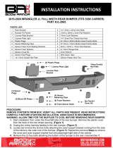
INSTALLATION INSTRUCTIONS
Page 1 of 4
JK Hiline Rear Bumper
PART #JL-2966
PARTS LIST:
1
Rear Bumper
4
14mm x 28mm x 3mm Flat Washers
2
Mesh Panels
4
6-1.0mm x 20mm Button Head Combo Bolts
2
14-1.75mm Double Nut Plate
4
6-1.0mm Flange Nuts
4
14-1.75mm x 40mm Hex Bolts
1
4mm Wrench
4
14mm Lock Washers
PROCEDURE:
REMOVE CONTENTS FROM BOX. VERIFY ALL PARTS ARE PRESENT. READ INSTRUCTIONS
CAREFULLY BEFORE STARTING INSTALLATION. ASSISTANCE IS RECOMMENDED. WARNING:
ALLOW TIME FOR THE MUFFLER TO COOL BEFORE REMOVING REAR BUMPER.
1. Start installation from under the rear bumper. Remove the hardware attaching the center of the bumper
to the crossmember, (Figure 1). NOTE: Assistance is recommended to hold the bumper in place as
hardware is removed. Next, remove the hardware attaching the outer bumper end to the end of the
bracket, (Figure 2). Repeat to release the passenger/right side of the bumper. With assistance, remove
the bumper from the end of the frame, (Figure 3).
2. Locate and remove the (2) hex bolts attaching the driver/left outer support bracket running from the side
of the frame to the outer end of the bumper, (Figure 3). Also remove the tow hook from the driver/left
side of the frame, (Figure 3). Repeat this Step to remove the outer support bracket from the
passenger/right side of the vehicle.
3. Optional light or Block Off Plate installation, (light sold separately).
a. Attach light to mounting tab on back of driver/left side of the Bumper, (Figure 4). NOTE: It may
be easier to install lights before attaching Bumper to vehicle.
b. If light will not be installed at this time, attach the included Block Off Plate to the tabs on the
back of the Bumper with the included (2) 6mm x 20mm Button Head Combo Bolts and (2) 6mm
Flange Nuts, (Figure 4).
c. Repeat the appropriate previous Step on the passenger/right side of the Bumper.
For Flush mount Cube Lights
(2) 14mm Double Nut Plates
(2) Mesh Panels

INSTALLATION INSTRUCTIONS
Page 2 of 4
a. Place the light onto the square hole and line up the light to the hole. Mark the holes on the side
of the light.
b. Drill the marked locations and attach the Cube Light.
c. Repeat the previous Steps for remaining light installation.
d. Follow light manufacturer’s instructions for adjustment and to properly wire the light to the
vehicle electrical system after Bumper installation.
4. Bumper is compatible with Swing Tire Mount, (available separately). Follow the instructions included
with the Tire Mount to attach the Spindle for the Swing Tire Mount to the back of the Bumper at this
time.
5. Select (1) 14mm Double Nut Plate. Insert the Nut Plate into the end of the driver/left side frame
channel, (Figure 5). Line up the hex nuts on the Nut Plate with the large slots in the side of the frame,
(Figure 6). Repeat to insert the remaining Double Nut Plate in the passenger/right side of the frame.
6. With assistance, carefully position the Rear Bumper Assembly up to the outside of the frame. Use the
provided (2) 14mm x 40mm Hex Bolts, (2) 14mm Lock Washers and (2) 14mm Flat Washers to attach
the Bumper to the 14mm Nut Plate inside the driver/left frame channel, (Figure 7). Reuse the (2)
factory bolts to attach the Bumper to the outside of the frame, (Figures 7 & 8). Leave hardware loose.
Repeat this Step to attach the passenger/right side of the Bumper to the outside of the frame.
7. Level and adjust the Rear Bumper and tighten all hardware at this time.
8. Do periodic inspections to the installation to make sure that all hardware is secure and tight.
To protect your investment, do not use any type of polish or wax that may contain abrasives that could damage the
finish. Mild soap may be used to clean Bumper
Rear
(Fig 2) Remove (2) outer bumper bracket bolts
(Fig 1) Remove (2) hex bolts attaching
bottom of bumper to frame cross member

INSTALLATION INSTRUCTIONS
Page 3 of 4
(Fig 3) Remove tow hook and outer bumper
bracket from driver/left side of frame (arrows)
Rear
Rear
Rear
(Fig 4) Attach Block Off Plate or light (available
separately) to tabs on back of Bumper (optional)
Tab for light
(Fig 5) Insert 14mm Double Nut Plate into
open end of frame (driver/left side pictured)
(Fig 6) Line up Double Nut Plate with slots
in side of frame (driver/left side pictured)

INSTALLATION INSTRUCTIONS
Page 4 of 4
Rear
Rear
(2) 14mm Hex Bolts
(2) 14mm Lock Washers
(2) 14mm Flat Washers
(Fig 8) Attach the driver/left side of the Bumper
to the Nut Plate in frame and threaded holes
Reuse (2) factory bolts
(Fig 7) Attach the driver/left side of the Bumper
to the Nut Plate in frame and threaded holes
/