Page is loading ...

ALUMINUM ELEVATION FRONT BUMPER
2017-22 FORD SUPER DUTY
Page 1 of 10 2/9/21 Rev1 (DP)
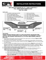
PARTS LIST:
1
Elevation Front Bumper Assembly
14
12-1.75mm x 50mm Hex Bolts
1
Driver/left Frame Bracket
22
12mm Lock Washers
1
Passenger/right Frame Bracket
22
12-1.75mm Hex Nuts
2
Plastic Plugs for license plate mount
2
8-1.25mm x 30mm Hex Bolts
1
Driver/left Light Mount (OEM LED)
2
8-1.25mm x 20mm Hex Bolts
1
Passenger/right Light Mount (OEM LED)
4
8mm x 28mm x 3mm Large Flat Washers
1
Driver/left Fog Light Block Off
4
8mm x 24mm x 2mm STD Flat Washers
1
Passenger/right Fog Light Block Off
4
8mm Nylon Lock Nuts
1
Driver/left Upper U-Bracket (OEM fog light)
3
6mm x 25mm Hex Bolts
1
Passenger/right Upper U-Bracket (OEM fog light)
6
6mm x 25mm Button Head Bolts
2
Lower U-Brackets (OEM fog light only)
4
6mm x 16mm Hex Bolts
1
ACC Adapter Bracket
19
6mm x 18mm x 1.6mm Flat Washers
1
Adaptive Cruise Control, (ACC) Driver/left Bracket
13
6mm Lock Washers
1
ACC Passenger/right side Bracket
9
6mm Hex Nuts
1
ACC Upper Bracket
1
4mm Wrench
1
ACC Plastic Cover
1
2.5mm Wrench
8
12mm x 50mm Bolt Plates
RECOMMENDED TO REPLACE THE 12MM HEX BOLTS ON AN ANNUAL BASIS
(2) License
Plate Plugs
Passenger/right Frame Bracket
Driver/left Frame Bracket
(8) 12mm
Bolt Plates
Driver/Left Upper
U-Bracket
Passenger/right
Upper U-Bracket
ACC Plastic
Cover
Right ACC
Bracket
Left ACC
Bracket
ACC Upper
Bracket
ACC Adapter
Bracket
(2) Lower
U-Brackets
Passenger/right
LED Light Insert
Driver/left LED
Light Insert
(8) 12mm Plastic
Washers
Passenger/right
Block Off
Driver/left
Block Off

ALUMINUM ELEVATION FRONT BUMPER
2017-22 FORD SUPER DUTY
Page 2 of 10 2/9/21 Rev1 (DP)
PROCEDURE:
REMOVE CONTENTS FROM BOX. VERIFY ALL PARTS ARE PRESENT. READ INSTRUCTIONS
CAREFULLY BEFORE STARTING INSTALLATION. BUMPER IS HEAVY, ASSISTANCE IS HIGHLY
RECOMMENDED TO AVOID POSSIBLE INJURY OR DAMAGE TO THE VEHICLE.
1. Remove the license plate and bracket. On models with factory fog lights, unplug both lights, (Figure 1).
Unplug and remove the adaptive cruise control, if equipped. Release the wiring harness from the clips
attached to the back of the bumper, (Figure 2). Move harness away from bumper.
2. Remove the bumper supports attaching the outer ends of the bumper to the outside of the frame,
(Figure 3). Remove the plastic covers surrounding the tow hooks, (Figures 4 & 5).
3. Place blocks or jack stands under the front bumper to support it during mounting bolt removal. Once the
bumper has been safely supported, remove the (8) factory bumper bolts, (Figure 5). Carefully slide the
bumper off over the tow hooks. WARNING! Assistance is required to hold the bumper in place during
bolt removal to prevent the bumper from falling.
4. Remove the tow hooks from the ends of the frame, (Figure 6). Next, remove the factory hex nuts, lower
frame extensions and double bolt plates from the end of the frame, (Figures 2 & 6).
5. Select the driver/left Frame Bracket, (Figure 7). Slide the Bracket over the end of the frame. Line up
the slots in the sides of the Bracket with the holes in the frame. Select (4) 12mm Bolt Plates. Insert the
Bolt Plates into the open end of the frame and out through the Bracket. Attach the Bracket to the Bolt
Plates with (4) 12mm Flat Washers, (4) 12mm Lock Washers and (4) 12mm Hex Nuts, (Figures 7 & 8).
Leave hardware loose.
6. Attach the top of the Bracket to the top of the frame with the included (4) 12mm x 50mm Hex Bolts, (8)
12mm Flat Washers, (4) 12mm Lock Washers and (4) 12mm Hex Nuts, (Figures 9 & 10). Do not fully
tighten hardware at this time.
7. Reuse the factory hardware to attach the driver/left tow hook to the bottom of the mounting tab on the
Frame Bracket, (Figure 10). NOTE: On models with ACC, driver side tow hook cannot be reinstalled.
8. Repeat Steps 5—7 to install the passenger/right Frame Bracket and tow hook.
9. Models with fog lights and/or sensor, disassemble factory bumper to remove fog light assemblies,
sensor and wiring harness.
10. Determine if vehicle is equipped with an adaptive cruise control, (ACC), and note the design of the
sensor. NOTE: The ACC assembly can also be installed after Bumper installation.
Vehicles without Adaptive Cruise Control, skip to Step 11.
All Models with Adaptive Cruise Control.
a. Select the Left ACC Bracket, Right ACC Bracket and ACC Upper Bracket, (Figure 11). Attach the
Left and Right ACC Brackets to the ACC Upper Bracket with (3) 6mm x 25mm Hex Bolts, (6) 6mm
Flat Washers, (3) 6mm Lock Washers and (3) 6mm Hex Nuts. Do not tighten hardware
Vehicles with “late” style ACC with tabs on top and bottom.
a. Select the Mounting Bracket Adapter Plate, (Figure 12).
b. Attach the ACC sensor to the back of the Adapter with the included (3) 6mm x 25mm Button Head
Bolts, (6) 6mm Flat Washers, (3) 6mm Lock Washers and (3) 6mm Hex Nuts, (Figure 12).
c. Insert (3) 6mm x 25mm Button Head Bolts through the (3) holes on the ACC Plastic Cover, the
ACC Bracket and out through the adaptive cruise control Adapter Plate. Secure with (3) 6mm Flat
Washers, (3) 6mm Lock Washers and (3) 6mm Hex Nuts, (Figure 13).
Vehicles with early style ACC with mounting tabs on ends.
a. Insert (3) 6mm x 25mm Button Head Bolts through the (3) holes on the ACC Plastic Cover, the
ACC Bracket and out through the adaptive cruise control. Secure with (3) 6mm Flat Washers, (3)
6mm Lock Washers and (3) 6mm Hex Nuts, (Figure 14).
Attach the ACC Bracket and sensor assembly to the mounting tab for the tow hook on the driver/left
Frame Bracket with (2) 8mm x 30mm Hex Bolts, (4) 8mm x 28mm Large Flat Washers and (2)
8mm Nylon Lock Nuts, (Figure 15). Tighten all ACC Bracket hardware.
11. Determine if vehicle is equipped with fog lights and type of light.
Models with rectangular factory fog lights:
a. Use a flat blade screwdriver to carefully pop out the tabs on the side of the fog light bracket
attaching the light to the bracket, (Figure 1). Pop the light out of the plastic bracket housing.
b. Remove the adjustment screw and spring from the light assembly.

ALUMINUM ELEVATION FRONT BUMPER
2017-22 FORD SUPER DUTY
Page 3 of 10 2/9/21 Rev1 (DP)
c. Select the driver/left top U-Bracket, (Figure 16). Attach the Bracket to the slot in the light opening
with the included (1) 8mm x 20mm Hex Bolt, (2) 8mm x 24mm STD Flat Washers and (1) 8mm
Nylon Lock Nut, (Figure 16).
d. Spread the sides of the Bracket enough to slide the OE plastic fog light between and into the
Bracket, (Figure 17). Select (1) Lower U-Bracket. Attach the Lower Bracket to the Upper Bracket
with (2) 6mm x 16mm Hex Bolts, (2) 6mm Lock Washers and (2) 6mm Flat Washers, (Figure 18).
e. Insert the factory spring between the tab on the Bracket and the light. Insert the screw through the
tab, spring and into the fog light, (Figure 18).
f. Repeat to install the passenger/right fog light.
Models with optional narrow factory LED Fog Light (2020-on models)
a. Remove the screws attaching the light to the plastic mount, (Figure 19).
b. Remove the preinstalled driver/left rectangular fog light mount insert from the back of the Elevation
Bumper, (Figure 20).
c. Select the driver/left LED light mount. Reuse the hardware to attach the Mount to the tabs on the
back of the Bumper, (Figure 21).
d. Reuse the factory screws to attach the LED fog light to the LED light mount, (Figure 21).
e. Repeat previous Steps to install the passenger/right LED Light Mount and light.
Models without fog lights.
a. Remove the preinstalled driver/left rectangular fog light mount insert from the back of the HD
Bumper, (Figure 21).
b. Select the driver/left Block Off. Reuse the hardware to attach the Block Off to the tabs on the back
of the Bumper, (Figure 21).
c. Repeat previous Steps to install the passenger/right Block Off.
12. Models with fog lights and/or ACC sensor, reinstall and plug in wiring harness.
13. With assistance, carefully position the Bumper Assembly up to the Brackets. Temporarily support the
weight of the Bumper. WARNING: To avoid possible injury or damage to the vehicle, do not proceed
until the bumper is fully and safely supported.
14. Line up the (3) holes in the driver/left side of the Bumper with the Frame Bracket. Attach the Bumper to
the Bracket with the included (3) 12mm x 50mm Hex Bolts, (3) 12mm Flat Washers, (3) 12mm Plastic
Washers, (3) 12mm Flat Washers, (3) 12mm Lock Washers and (3) 12mm Hex Nuts, (Figures 22 &
23). NOTE: Insert the Plastic Washers between the outer 12mm Flat Washers and the mounting plate
on the back of the Bumper to minimize corrosion. Do not fully tighten hardware at this time. Repeat to
attach the passenger/right side of the Bumper to the Bracket.
15. Level and adjust the bumper and fully tighten all hardware.
16. Use the included (2) push-in plastic nuts to attach the front license plate, (if required), to the (2) holes in
the front bumper, (Figure 24).
17. On models with grille mounted factory camera, remove the center screen, (Figure 24).
18. Reattach the factory harness. Adjust lights and tighten all fog light bracket hardware.
19. Do periodic inspections to the installation to make sure that all hardware is secure and tight.
To protect your investment, Do not use any type of polish or wax that may contain abrasives that could damage the
finish. Mild soap may be used to clean the Elevation Front Bumper assembly.
Regular washing is required in extreme environments to help prevent deposits of corrosive salts.

ALUMINUM ELEVATION FRONT BUMPER
2017-22 FORD SUPER DUTY
Page 4 of 10 2/9/21 Rev1 (DP)
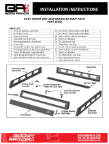
Driver/left Side Installation Pictured
WARNING! Do not remove bumper bolts
unless the bumper is properly supported
on blocks or stands or it may fall.
(Fig 4) Remove plastic cover around tow hook
(Fig 1) On models with fog lights, unplug
wire harness from back of light
(Fig 2) Release clips attaching the wire
harness for fog lights if equipped (driver side)
(Fig 3) Remove outer bumper support
brackets between frame and bumper (arrow)
Lower frame
extension
Front
(Fig 5) Remove bumper bolts (driver side pictured)
Front

ALUMINUM ELEVATION FRONT BUMPER
2017-22 FORD SUPER DUTY
Page 5 of 10 2/9/21 Rev1 (DP)
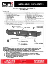
Driver/left Side Installation Pictured
(Fig 6) Remove tow hook assembly and lower
frame extension (not pictured-see Fig 2)
(4) 12mm Flat Washers
(4) 12mm Lock Washers
(4) 12mm Hex Nuts
(4) 12mm x 50mm Hex Bolts
(8) 12mm Flat Washers
(4) 12mm Lock Washers
(4) 12mm Hex Nuts
Front
(Fig 7) Insert Bolt Plates into open end of
frame. Attach Bracket to sides of frame
Front
(4) 12mm
Bolt Plates
Front
Front
(Fig 9) Attach top of Bracket to top of frame
(Fig 8) Insert Bolt Plates into open end of
frame (driver/left frame Bracket pictured)
WARNING! Do not remove bumper bolts
unless the bumper is properly supported
on blocks or stands or it may fall.

ALUMINUM ELEVATION FRONT BUMPER
2017-22 FORD SUPER DUTY
Page 6 of 10 2/9/21 Rev1 (DP)
Front
(Fig 10) Reuse factory hardware to attach tow
hook to Bracket (do not reinstall tow hook on
driver/left side on models with ACC sensor)
Attach top of Bracket
to top of frame
(Fig 11) Vehicles equipped with adaptive cruise
control, ACC, Bracket assembly illustrated
Front
(3) 6mm x 25mm Hex Bolts
(6) 6mm Flat Washers
(3) 6mm Lock Washers
(3) 6mm Hex Nuts
(3) 6mm Button Head Bolts
(3) 6mm Flat Washers
(3) 6mm Lock Washers
(3) 6mm Hex Nuts
Right ACC Bracket
ACC Upper
Bracket
(Fig 12) Attach “Late” ACC sensor
to back of Adapter Bracket
Front
“Late” Adaptive
Cruise Control
Left ACC Bracket
(Fig 13) Attach Adapter Bracket with “Late”
ACC sensor to back of Mounting Brackets,
(Fig 16) and attach Plastic Cover to front
Adapter Bracket with
“Late” Adaptive Cruise
Control sensor
Plastic Cover
Front

ALUMINUM ELEVATION FRONT BUMPER
2017-22 FORD SUPER DUTY
Page 7 of 10 2/9/21 Rev1 (DP)
(Fig 16) Rectangular fog light installation (light
not included). Attach driver/left Upper Bracket
to the slot in top of the opening
8mm x 20mm Hex Bolt
(2) 8mm x 24mm Flat Washers
8mm Nylon Lock Nut
Front
(Fig 17) Carefully spread sides to slide OEM
fog light into position in pivot holes
Front
(Fig 14) Attach “Early” ACC sensor to
back of Mounting Brackets, (Fig 16)
and Plastic Cover to front
Front
(Fig 15) ACC assembly attached to the
Driver/left side Frame Bracket illustrated
Front
(2) 8mm x 30mm Hex Bolts
(4) 8mm x 28mm Flat Washers
(2) 8mm Nylon Lock Nuts
“Early” Adaptive
Cruise Control
(3) 6mm Button Head Bolts
(3) 6mm Flat Washers
(3) 6mm Lock Washers
(3) 6mm Hex Nuts
Plastic Cover

ALUMINUM ELEVATION FRONT BUMPER
2017-22 FORD SUPER DUTY
Page 8 of 10 2/9/21 Rev1 (DP)
Driver/left Side Installation Pictured
Front
(Fig 18) Attach lower U Bracket to Upper
Bracket. Reuse factory adjustment
hardware (screw, spring and plastic nut)
6mm x 16mm Hex Bolt
6mm Lock Washer
6mm Flat Washer
(Fig 19) Remove screws to remove
narrow LED fog light from plastic mount
(Fig 20) Remove fog light mount from back
of Bumper (driver/left side illustrated)
WARNING! Do not crawl under bumper
unless it is properly supported on blocks
or stands or the bumper may fall.
Front
Front
(Fig 21) Models with LED fog lights only,
reuse screws to attach LED fog light to
Light Mount. Reuse hardware to attach
LED Fog Light assembly or Block Offs to
tabs on back of Bumper
Block Off
LED Light
Mount

ALUMINUM ELEVATION FRONT BUMPER
2017-22 FORD SUPER DUTY
Page 9 of 10 2/9/21 Rev1 (DP)
Driver/left Side Installation Pictured
(3) 12mm x 50mm Hex Bolts
(6) 12mm Flat Washers
(3) 12mm Lock Washers
(3) 12mm Hex Nuts
(Fig 22) Attach Bumper to side of Bracket.
NOTE: Insert Plastic Washers between
Flat Washer and mounting plate on
Bumper to minimize corrosion
(Fig 23) Attach Bumper to side of Bracket
(driver/left side pictured from behind bumper)
WARNING! Do not crawl under bumper
unless it is properly supported on blocks
or stands or the bumper may fall.
Front
Front
(Fig 24) Remove center screen if equipped
with grille mounted camera. Push plastic
plugs into holes in Bumper for license plate
Complete Installation
(3) 12mm Plastic Washers
Special Note: While Aluminum does not rust,
there is potential for galvanic corrosion if the
coating is scratched between your bumper and
the steel frame brackets + hardware (especially
in extreme environments such as the coastlines
or where road salt is used during winter). A
visual inspection should be performed by the
user at least on an annual basis to determine if
excessive corrosion is present on or surrounding
the hardware.

ALUMINUM ELEVATION FRONT BUMPER
2017-22 FORD SUPER DUTY
Page 10 of 10 2/9/21 Rev1 (DP)
Supplemental Installation Steps: Some 2022 F-350’s will have an extra cooler between frame.
• Trim tabs off OE cooler brackets so they rest flat against the bumper brackets:
• Install cooler onto forward bolt plate:
/