Page is loading ...

LDP-8242
Multi-Definition Loudness Processor
User Manual

LDP-8242 User Manual
• Ross Part Number: 8242DR-004-04
• Release Date: February 26, 2013.
The information in this manual is subject to change without notice or obligation.
Copyright
© 2013 Ross Video Limited. All rights reserved.
Contents of this publication may not be reproduced in any form without the written permission of
Ross Video Limited. Reproduction or reverse engineering of copyrighted software is prohibited.
Patents
This product is protected by the following US Patents: 4,205,346; 5,115,314; 5,280,346;
5,561,404; 7,304,886; 7,508,455; 7,602,446; 7,834,886; 7,914,332. This product is protected by
the following Canadian Patents: 2039277; 1237518; 1127289. Other patents pending.
Notice
The material in this manual is furnished for informational use only. It is subject to change without
notice and should not be construed as commitment by Ross Video Limited. Ross Video Limited
assumes no responsibility or liability for errors or inaccuracies that may appear in this manual.
Trademarks
• is a registered trademark of Ross Video Limited.
• Ross, ROSS, ROSS®, and MLE are registered trademarks of Ross Video Limited.
• openGear® is a registered trademark of Ross Video Limited.
• DashBoard Control System™ is a trademark of Ross Video Limited.
• Linear Acoustic® is a registered trademark of Linear Acoustic, Inc. 2.0-to-5.1 audio
upmixer licensed feature uses the AutoMAX-II™ upmix algorithm provided under
license from Linear Acoustic Inc. Loudness processor licensed feature uses
AEROMAX™ algorithms provided under license from Linear Acoustic Inc. Linear
Acoustic, the “LA” symbol, UPMAX, AutoMAX, AutoMAX-II, and AEROMAX are
trademarks of Linear Acoustic Inc. All rights reserved.
• All other product names and any registered and unregistered trademarks mentioned in
this manual are used for identification purposes only and remain the exclusive property of
their respective owners.

Important Regulatory and Safety Notices to Service Personnel
Before using this product and nay associated equipment, refer to the “Important Safety
Instructions” listed below to avoid personnel injury and to prevent product damage.
Product may require specific equipment, and/or installation procedures to be carried out to satisfy
certain regulatory compliance requirements. Notices have been included in this publication to call
attention to these specific requirements.
Symbol Meanings
Important Safety Instructions
This symbol on the equipment refers you to important operating and maintenance (servicing)
instructions within the Product Manual Documentation. Failure to heed this information may
present a major risk of damage to persons or equipment.
Warning — The symbol with the word “Warning” within the equipment manual indicates a
potentially hazardous situation, which, if not avoided, could result in death or serious injury.
Caution — The symbol with the word “Caution” within the equipment manual indicates a
potentially hazardous situation, which, if not avoided, may result in minor or moderate injury. It
may also be used to alert against unsafe practices.
Notice — The symbol with the word “Notice” within the equipment manual indicates a
potentially hazardous situation, which, if not avoided, may result in major or minor equipment
damage or a situation which could place the equipment in a non-compliant operating state.
ESD Susceptibility — This symbol is used to alert the user that an electrical or electronic
device or assembly is susceptible to damage from an ESD event.
Caution — This product is intended to be a component product of the DFR-8300 series
frame. Refer to the DFR-8300 Series Frame User Manual for important safety instructions
regarding the proper installation and safe operation of the frame as well as its component
products.
Warning — Certain parts of this equipment namely the power supply area still present a
safety hazard, with the power switch in the OFF position. To avoid electrical shock, disconnect
all A/C power cords from the chassis’ rear appliance connectors before servicing this area.
Warning — Service barriers within this product are intended to protect the operator and
service personnel from hazardous voltages. For continued safety, replace all barriers after any
servicing.
This product contains safety critical parts, which if incorrectly replaced may present a risk of
fire or electrical shock. Components contained with the product’s power supplies and power
supply area, are not intended to be customer serviced and should be returned to the factory for
repair. To reduce the risk of fire, replacement fuses must be the same time and rating. Only use
attachments/accessories specified by the manufacturer.

EMC Notices
United States of America
FCC Part 15
This equipment has been tested and found to comply with the limits for a class A Digital device,
pursuant to part 15 of the FCC Rules. These limits are designed to provide reasonable protection
against harmful interference when the equipment is operated in a commercial environment. This
equipment generates, uses, and can radiate radio frequency energy and, if not installed and used
in accordance with the instruction manual, may cause harmful interference to radio
communications. Operation of this equipment in a residential area is likely to cause harmful
interference in which case the user will be required to correct the interference at their own
expense.
CANADA
This Class “A” digital apparatus complies with Canadian ICES-003.
Cet appareil numérique de la classe “A” est conforme a la norme NMB-003 du Canada.
EUROPE
This equipment is in compliance with the essential requirements and other relevant provisions of
CE Directive 93/68/EEC.
INTERNATIONAL
This equipment has been tested to CISPR 22:1997 along with amendments A1:2000 and
A2:2002, and found to comply with the limits for a Class A Digital device.
Maintenance/User Serviceable Parts
Routine maintenance to this openGear product is not required. This product contains no user
serviceable parts. If the module does not appear to be working properly, please contact Technical
Support using the numbers listed under the “Contact Us” section on the last page of this manual.
All openGear products are covered by a generous 5-year warranty and will be repaired without
charge for materials or labor within this period. See the “Warranty and Repair Policy” section in
this manual for details.
Notice — Changes or modifications to this equipment not expressly approved by Ross Video
Limited could void the user’s authority to operate this equipment.
Notice — This is a Class A product. In domestic environments, this product may cause radio
interference, in which case the user may have to take adequate measures.

Environmental Information
The equipment that you purchased required the extraction and use of natural
resources for its production. It may contain hazardous substances that could
impact health and the environment.
To avoid the potential release of those substances into the environment and to diminish the need
for the extraction of natural resources, Ross Video encourages you to use the appropriate
take-back systems. These systems will reuse or recycle most of the materials from your
end-of-life equipment in an environmentally friendly and health conscious manner.
The crossed out wheelie bin symbol invites you to use these systems.
If you need more information on the collection, reuse, and recycling systems, please contact your
local or regional waste administration.
You can also contact Ross Video for more information on the environmental performance of our
products.

Company Address
Ross Video Limited Ross Video Incorporated
8 John Street P.O. Box 880
Iroquois, Ontario, K0E 1K0 Ogdensburg, New York
Canada USA 13669-0880
General Business Office: (+1) 613 • 652 • 4886
Fax: (+1) 613 • 652 • 4425
Technical Support: (+1) 613 • 652 • 4886
After Hours Emergency: (+1) 613 • 349 • 0006
E-mail (Technical Support): tech[email protected]
E-mail (General Information): solutions@rossvideo.com
Website: http://www.rossvideo.com

LDP-8242 User Manual (Iss. 04) Contents • i
Contents
Introduction 1
Overview.............................................................................................................................. 1-2
Features.................................................................................................................. 1-2
Video/Audio Signal Types .................................................................................... 1-3
Video and Audio Options...................................................................................... 1-3
Control and Data Inputs/Outputs........................................................................... 1-3
Supported Audio and Video Formats .................................................................... 1-4
Manual Overview ................................................................................................................ 1-5
Card Software Versions and this Manual.............................................................. 1-5
Functional Block Diagram................................................................................................... 1-6
Video Subsystem Overview................................................................................................. 1-7
Video Processor..................................................................................................... 1-7
Frame Sync Function............................................................................................. 1-7
Timecode Processor............................................................................................... 1-7
Closed Captioning Processor................................................................................. 1-8
Audio Subsection Overview ................................................................................................ 1-9
Audio Processing Overview.................................................................................. 1-9
Audio Input Routing/Mixing Function................................................................ 1-10
Audio Output Routing Function.......................................................................... 1-12
Upmixer Licensed Feature (UMA-8242) ............................................................ 1-12
Loudness Processor ............................................................................................. 1-13
Tone Generators .................................................................................................. 1-14
Control and Data Input/Output Interfaces ......................................................................... 1-15
Rear Modules....................................................................................................... 1-15
GPI Interface ....................................................................................................... 1-15
Serial (COMM) Ports .......................................................................................... 1-15
User Control Interface ....................................................................................................... 1-16
DashBoard™ User Interface ............................................................................... 1-16
Documentation Terms and Conventions............................................................................ 1-17
Warnings, Cautions, and Notes ........................................................................... 1-17
Installation 2
Before You Begin ................................................................................................................2-2
Static Discharge..................................................................................................... 2-2
Unpacking.............................................................................................................. 2-2
Installing a Rear Module...................................................................................................... 2-3
Installing a Rear Module ....................................................................................... 2-3
Installing a Card................................................................................................................... 2-4
Installing the LDP-8242 ........................................................................................ 2-4
Cabling for the LDP-8242 ................................................................................................... 2-5
Cabling Overview.................................................................................................. 2-5
Setting up Network Remote Control ................................................................................... 2-8
Operating Instructions 3
Control and Display Descriptions........................................................................................ 3-2

ii • Contents LDP-8242 User Manual (Iss. 04)
Function Submenu/Parameter Submenu Overview............................................... 3-2
Card-edge Controls, Indicators, and Display .......................................................................3-3
Card-edge Controls................................................................................................3-3
DashBoard™ User Interface ................................................................................................ 3-5
Accessing the Card via DashBoard™.................................................................................. 3-6
Accessing the Card via DashBoard .......................................................................3-6
Checking Card Information.................................................................................................. 3-8
Ancillary Data Line Number Locations and Ranges ........................................................... 3-9
Function Submenu List and Descriptions ..........................................................................3-10
Troubleshooting .................................................................................................................3-51
Error and Failure Indicator Overview..................................................................3-51
Basic Troubleshooting Checks ............................................................................ 3-55
Processing Error Troubleshooting .......................................................................3-55
In Case of Problems............................................................................................. 3-56
Specifications 4
Technical Specifications ......................................................................................................4-2
Service Information 5
Troubleshooting Checklist ...................................................................................................5-2
Warranty and Repair Policy ................................................................................................. 5-3

LDP-8242 User Manual (Iss. 04) Introduction • 1–1
Introduction
In This Chapter
This chapter contains the following sections:
• Overview
• Manual Overview
• Functional Block Diagram
• Video Subsystem Overview
• Audio Subsection Overview
• Control and Data Input/Output Interfaces
• User Control Interface
• Documentation Terms and Conventions
A Word of Thanks
Congratulations on choosing an openGear LDP-8242 Multi-Definition Loudness Processor. Your
LDP-8242 is part of a full line of Digital Products within the openGear Terminal Equipment
family of products, backed by Ross Video’s experience in engineering and design expertise since
1974.
You will be pleased at how easily your new LDP-8242 fits into your overall working
environment. Equally pleasing is the product quality, reliability and functionality. Thank you for
joining the group of worldwide satisfied Ross Video customers!
Should you have a question pertaining to the installation or operation of your LDP-8242, please
contact us at the numbers listed on the back cover of this manual. Our technical support staff is
always available for consultation, training, or service.

1–2 • Introduction LDP-8242 User Manual (Iss. 04)
Overview
The LDP-8242 is ideal for correcting irritating loudness differences between programs and
commercials. Featuring 24-bit audio processing that supports 16 channels of embedded audio
from an HD/SD-SDI signal.
With Linear Acoustic AEROMAX™ technology, the card applies loudness control on up to six
channels of audio from any of the 16 channels of embedded audio. Linear Acoustic
AEROMAX™ algorithms use a sophisticated multi-band approach to loudness processing. These
algorithms can apply multifaceted loudness correction specifically targeted to various frequency
ranges and other characteristics within the program material, resulting in audio free from abrupt
loudness or image shifts while preserving more of the original content than previously possible.
Because the card processes audio loudness locally and in sync with the video, loudness is
processed without the accumulated latency delay found in other loudness processors.
An optional discrete AES option provides 16 channels of discrete audio support, with 8 AES pair
BNCs, which can be configured as inputs or outputs. The AES-8242 option provides discrete
audio loudness processing as well as 16 channel embedding / de-embedding.
Optional Linear Acoustic UPMAX upmixing technology allows legacy stereo program audio to
be converted to 5.1 channel audio, with the UMA-8242 option.
Features
The LDP-8242 includes the following features:
• Loudness Processing with Linear Acoustic AEROMAX™ algorithm
• Actively and automatically corrects irritating loudness level changes
• Automatic video delay to match audio processing delay
• Loudness control for stereo or 5.1 audio
• Sophisticated multi-band processing
• Audio channel mapping, phase inversion and level control
• 16 channels of sample rate conversion
• Passes all audio channels
• 16 channel embedding and de-embedding
• Passive relay bypass for SDI coax input/output path
• Handles all popular formats of SD (270Mbps) and HD (1.485Gbps) signals
• Reports status and configuration remotely via the DashBoard Control System™
• 5-year transferable warranty

LDP-8242 User Manual (Iss. 04) Introduction • 1–3
Video/Audio Signal Types
Table 1.1 lists the video/audio inputs and outputs provided by the LDP-8242. Note that some
signal types are supported through the use of options.
Video and Audio Options
In addition to the I/O options described in Table 1.1, the LDP-8242 offers the video and audio
options described in Table 1.2.
Control and Data Inputs/Outputs
Table 1.3 lists the control and data input/output interfaces (available via the rear module
connections) provided by the LDP-8242.
Table 1.1 Video/Audio Signal Types
Signal ID Description
Option/Rear Module
Package Required
SDI IN A HD-SD-SDI BNC video input Standard
AES Audio IN/OUT
(1-16)
Eight AES 3-id BNC pairs; each pair
user GUI-selectable as either input or
output. Independent SRC for each
input, with auto/manual SRC bypass
for non-PCM data.
AES-8242 licensed option
SDI OUT A HD-SD-SDI BNC video output Standard
Note: The input/output complement listed above and shown in Figure 1.1 and Figure 1.3 represent the
maximum capability of the LDP-8242.
Table 1.2 Video/Audio Options
Option Description
Option/Rear Module
Package Required
Added second Linear
Acoustic™ Loudness
Processing function
In addition to base loudness processor,
a second Linear Acoustic™
AEROMAX™ 5.1-channel or stereo
audio output loudness processing can
be added.
Standard
Linear Acoustic™
Upmixing software
Linear Acoustic™ AUTOMAX™
converts legacy stereo program audio
(from any source received by the card)
to 5.1-channel audio).
UMA-8242 licensed option
Table 1.3 Control and Data Input/Output Interfaces
Signal ID Description
GPI 1, 2
Two ground-closure sensing GPI inputs (each sharing common
ground connection at chassis potential). GPI activation invokes a
user-specified card control preset. Refer to the section “Control
and Data Input/Output Interfaces” on page 1-15 for information.
COMM 1, 2
Two serial Rx/Tx ports, each individually configurable as RS-485
or RS-232. Refer to the section “Control and Data Input/Output
Interfaces” on page 1-15 for information.

1–4 • Introduction LDP-8242 User Manual (Iss. 04)
Supported Audio and Video Formats
Table 1.4 provides details regarding the audio and video formats supported by the LDP-8242.
Table 1.4 Supported Audio and Video Formats
Item Description/Specification
Input / Output
Video
Raster Structure: Frame Rate:
1080i
a
a. All rates displayed as frame rates; interlaced (“i”) field rates are two times the rate
value shown.
25; 29.97
720p 50; 59.94
486i
a
29.97
575i
a
25
Embedded
Audio
The LDP-8242 supports all four groups (16 channels) of embedded audio
at full 24-bit resolution in both SD (with extended data packets) and HD.
Discrete AES
Audio
The AES-8242 licensed option enables the LDP-8242 to accept 16
channels (8 pairs) of discrete AES audio on 75W BNC connections
(maximum total of inputs and outputs). Sample rate conversion can be
employed to accommodate sample rate differences in the AES stream and
the input video stream.

LDP-8242 User Manual (Iss. 04) Introduction • 1–5
Manual Overview
This manual provides installation and operating instructions for the LDP-8242.
This manual consists of the following chapters:
• Introduction — Provides information about this manual and what is covered. Also
provides general information regarding the LDP-8242.
• Installation — Provides instructions for installing the LDP-8242 in a frame, and
optionally installing a rear module.
• Operating Instructions — Provides overviews of operating controls and instructions for
using the LDP-8242.
• Specifications — Provides the technical specifications for the LDP-8242.
• Service Information — Provides troubleshooting solutions and warranty information.
Card Software Versions and this Manual
When applicable, Ross Video provides for continual openGear product enhancements through
software updates. As such, functions described in this manual may pertain specifically to cards
loaded with a particular software build. If you received your LDP-8242 card and this manual at
the same time, this manual reflects all facets of your card.
The software version of your card can be checked by viewing the Info submenu on the card-edge
display, or by checking the Card Info menu in DashBoard™. Refer to the section “Checking
Card Information” on page 3-8 for more information. This section provides guidance when
your card software does not match this manual.
Card software is an earlier version
Card is not loaded with the latest software. Not all functions and/or specified performance
described in this manual may be available.
You can update your card by:
1. Contacting Ross Technical Support.
2. Downloading the latest firmware and/or software for your card onto your computer.
3. Uploading the new firmware and/or software to your card through DashBoard™.
Card software is a newer version
A new manual is expediently released whenever a card’s software is updated and specifications
and/or functionality have changed as compared to an earlier version (a new manual is not
necessarily released if specifications and/or functionality have not changed). A manual earlier
than a card’s software version may not completely or accurately describe all functions available
for your card.
If your card shows features not described in this manual, you can check for the latest manual (if
applicable) and download it by going to our website.

1–6 • Introduction LDP-8242 User Manual (Iss. 04)
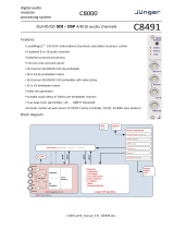
Functional Block Diagram
The base model LDP-8242 provides Linear Acoustic™ loudness processing with frame sync,
video processing, embedded audio support, and timecode support. (Figure 1.1) The various
options are described in detail in the section “Video and Audio Options” on page 1-3, and as
applicable throughout this manual.
This section provides a functional block diagram that outlines the workflow of the LDP-8242.
Note that signal connections shown depicts full input/output capability. Practical input/output
signal availability is determined by the licensed features installed.
Figure 1.1 Simplified Block Diagram — LDP-8242
PGM VIDEO
RECLOCKED
OUTPUT
CROSSPOINT
HD/SD-SDI OUT
BNC A
HD/SD-SDI OUT
BNC B
HD/SD-SDI OUT
BNC C
HD/SD-SDI OUT
BNC D
ETHERNET 10/100
(ON FRAME)
DASHBOARD™
MONITOR/CONTROL
TIMECODE,
CC, AFD
AUDIO
MUX
AUDIO PROCESSING
LOUDNESS PROCESSING, AUDIO ROUTING,
MIXING, LEVEL CONTROL, TONE GENERATION
DOWNMIXING, RATE CONVERSION,
SMOOTH DELAY ADJUMSTMENT
UPMIXING AVAILABLE WITH THE
UM-8242 LICENSED OPTION
PGM VIDEO
RECLOCKED (SDI INPUT A ONLY)
AUDIO
DEMUX
FRAME
SYNC
REFERENCE TIMECODE EXTRACT
REF DETECT /
FALLOVER
RELAY
BYPASS†
FRAME REF 1
FRAME REF 2
GPIO
GPIO-BASED CONTROL
EQ,
RECLOCK,
INPUT
MAP
HD/SD-SDI IN
BNC A
HD/SD-SDI IN
BNC B
HD/SD-SDI IN
BNC C
HD/SD-SDI IN
BNC D
AES
SRC
AES AUDIO IN
16-CHANNEL
BNC (8 PAIRS)*
†
Bypass relay fully passive failover located on the rear module. Card presence not required for passive failover connection.
Relay bypass is available only between the SDI IN B and SDI OUT B ports.
*Available with the AES-8242 licensed option.
AES
TRANSMITTER
AES AUDIO
16-CHANNEL
BNC (8 PAIRS)*

LDP-8242 User Manual (Iss. 04) Introduction • 1–7
Video Subsystem Overview
Descriptions below include some functions and features that are available only as options.
The LDP-8242 features a frame sync that can select from either of two card frame reference
sources, or free-run input video sync. In the event of input video loss of signal, the output can be
set to disable video, go to black, go to an internal test signal generator pattern, or freeze to the last
intact frame (last frame having valid SAV and EAV codes).
Video Processor
The LDP-8242 provides full color processing control (luma gain and lift, chroma saturation, and
color phase) of the output video. The color correction function can be user-selected to be applied
to input video or output video as shown in Figure 1.3.
Frame Sync Function
This function provides for frame sync control using either one of two external FRAME REF IN
(1,2) reference signals distributed with the DFR-8321 series frame, or the input video as a frame
sync reference.
This function also allows horizontal and/or vertical offset to be added between the output video
and the frame sync reference.
An internal test signal generator provides a selection of 10 standard patterns such as color bars,
sweep patterns, and other technical patterns. The generator output can be invoked upon loss of
program video input, or applied to the program video output via user controls.
Timecode Processor
This function uses extracted timecode data from the input video (waveform or ATC), reference
VITC waveform, or internal (free run) and in turn re-inserts selected timecode data into the
program video signal.(Figure 1.2) The function can monitor video input and reference input for
supported timecode formats, and then select and prioritize among SDI VITC waveform, SDI
ATC_VITC, and SDI ATC_LTC timecode sources. If the preferred format is detected, the
preferred format is used by the card; if the preferred format is not detected, the card uses other
formats (where available) as desired.
The function also provides conversion between various timecode formats and provides
independent insertion and line number controls for each SDI timecode output format.

1–8 • Introduction LDP-8242 User Manual (Iss. 04)
Figure 1.2 Timecode Processor
Closed Captioning Processor
This function provides support for closed captioning setup. When enabled, the function allows
passage of timecode data. The function also allows the selection of the ancillary data line number
where the ancillary closed caption data is outputted when the output is HD.

LDP-8242 User Manual (Iss. 04) Introduction • 1–9
Audio Subsection Overview
Descriptions below include some functions and features that are available only as options.
Audio Processing Overview
The LDP-8242 audio processing subsection is built around a card internal 16-channel bus. This
16-channel bus receives inputs from an input routing crosspoint that routes de-embedded and
discrete AES signals over the 16-channel bus. Correspondingly, at the output end of the
16-channel bus is an output routing crosspoint that in turn distributes the 16-channel bus signals
to embedded and discrete AES audio outputs. An Audio DSP function (which interfaces with the
output routing block) provides eight tone generators and advanced functions such as loudness
processing and upmixing. The routing and Audio DSP functions are described in detail later in
this section.
As such, the audio subsection provides a full crosspoint between all supported audio inputs and
output formats.
The audio subsection allows choices from the following audio inputs:
• 16 channels of de-embedded audio from the SDI program video path
• Up to 16 channels (8 pairs) of discrete AES input
• Up to 10 channels of decoded Dolby® E or AC-3 audio
• Digital silence (mute) setting
The audio subsection allows routing to the following audio outputs:
• 16 channels of embedded audio on the SDI output
• Up to 16 channels of discrete AES output on eight AES pairs
All embedded and AES channels have status displays that show the following for each channel
pair:
• PCM signal presence
• Dolby® E® signal presence
• Dolby® Digital® signal presence
• Missing (no signal detected)
Embedded, and AES input channel pairs also have displays showing slow-ballistics true peak
levels for each pair. Embedded and AES channels at digital silence signal level show Mute.
Output audio rates are always 48 kHz locked to output video, but discrete AES inputs can pass
through the sample rate converters to align these inputs with the output timing. Output AES is
always precisely synchronized with the output video.
Note — Practical AES channel count handled by the card is 8 pairs, of which each
pair can be user GUI-selectable as an input or output.

1–10 • Introduction LDP-8242 User Manual (Iss. 04)
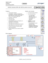
Figure 1.3 Audio Block Diagram
Audio Input Routing/Mixing Function
The input routing function provides gain and mute controls for each input signal. (Figure 1.3)
Following these controls, selected inputs can directly exit the input routing function and be
applied to the internal bus, or first be applied to one of four downmixers or flex mixers.
Downmixers
Four independent downmixers (Downmix-A thru Downmix-D) provides for the selection of any
five embedded, AES discrete, Dolby® decoded, or analog audio sources serving as Left (
L),
Right (
R), Center (C), Left Surround (Ls), and Right Surround (Rs) individual signals to be
multiplexed into a stereo pair. The resulting stereo pairs
Downmix-A(L/R) thru Downmix-D(L/R)
can in turn be routed and processed just like any of the other audio sources described earlier. See
Figure 1.4 for an example.

LDP-8242 User Manual (Iss. 04) Introduction • 1–11
Figure 1.4 Downmixing Functional Block Diagram with Example Sources
Flex Mixer
The Flex Mixer is a flexible-structure mixer in which any of 16 summing nodes (Flex Mix Bus A
thru
Flex Mix Bus P) can be applied to any of the 16 inputs, thereby allowing several
customizable mixing schemes. Any individual input row can be assigned to any of the Flex Mix
buses.
Using this scheme, full cross-point mixing of PCM signals can be achieved within the limit of
available Flex Mix buses, and eventually applied to any of the internal bus channels. Figure 1.5
shows an example of two independent 3-to-1 mono mixers availed by setting inputs (rows) 1 thru
3 to use virtual flex mix bus
Flex Mix Bus A, and by setting inputs 4 thru 6 to use virtual flex mix
bus
Flex Mix Bus B. The Flex Mix Bus A and Flex Mix Bus B virtual outputs can then be routed
over any of the internal bus channels. In this example, because rows 1 thru 3 are all applied in
common to mixer node
Flex Mix Bus A, the Flex Mix Bus A output is the mono-mixed sum of
these inputs. The mono mix on the
Flex Mix Bus B node similarly produces a mono mix of input
rows 4 thru 6.
Figure 1.5 Flex Mixer with Dual Mono Mixer Example
Internal Bus
The internal bus receives its audio inputs from the input routing function and accommodates a
maximum of 16 concurrent channels. This conduit serves as a centralized point for managing
audio delay offset from video and master gain controls for outputs from the input routing
function.

1–12 • Introduction LDP-8242 User Manual (Iss. 04)
A bulk (master) video/audio delay function allows adding or reducing audio delay from the video
delay. The LDP-8242 re-establishes video/audio sync following framesync changes by applying
an offset in small, progressive amounts to provide a seamless, glitch-free retiming.
In addition to the master sync/delay controls, each bus channel has its own independent delay and
gain control.
As shown in Figure 1.3, the internal bus receives inputs directly from card external sources as
listed below.
•Emb Ch 1-16
•AES Ch 1-16
• Silence
Audio Output Routing Function
The output routing function provides routing to card outputs. This function can also direct
internal bus signals to further mixing capabilities or advanced Audio DSP functions. This
function also provides gain and mute controls for each signal.
Audio DSP functions include 5.1-channel and stereo loudness processing, and upmixing.
The Audio DSP block provides the function complement (selected via user controls) listed below.
Because this block is entirely software-based, it can provide the Audio DSP combinations listed
below (depending on ordered options).
• 5.1-Ch Loudness Processor
• 5.1-Ch Loudness Processor + Upmixer
Upmixer Licensed Feature (UMA-8242)
The 2.0-to-5.1 Upmixer function receives a normal PCM stereo pair from any internal bus
channel pair. The stereo pair is upmixed to provide 5.1 channels (Left (
L), Right (R), Center (C),
Low Frequency Effects (
LFE), Left Surround (Ls), and Right Surround (Rs)). Whenever the
upmixer is active, it overwrites the six selected 5.1 output channels with the new 5.1 upmix
signals (including replacing the original source stereo
L and R inputs with new L and R signals).
The 2.0-to-5.1 upmixer can be set to upmix in any of three modes: Always upmix, Bypass upmix,
or Auto enable/bypass upmixing. The Auto upmixing mode looks at the signal levels on the
selected channels and compares them to a selectable level threshold. It then determines whether
or not to generate 5.1 upmixing from the stereo pair as follows:
• If the upmixer detects signal level below a selected threshold on all three of the selected
channels designated as
C, Ls, and Rs, this indicates to the upmixer that these channels are
not carrying 5.1. In this case, the upmixer produces new 5.1 content generated by the
upmixer.
• If the upmixer detects signal level above a selected threshold on any of the three selected
channels designated as
C, Ls, and Rs, this indicates to the upmixer that the channel(s) are
already carrying viable 5.1 content. In this case, the upmixer is bypassed and the channels
fed to the upmixer pass unaffected to the upmixer outputs.
The examples in Figure 1.6 and Figure 1.7 show the automatic enable/disable upmixing function
applied to example selected channels
Bus Ch 1 thru Bus Ch 6. As shown and described, the
processing is contingent upon the signal levels of the channels selected to carry the new 5.1
upmix relative to the selected threshold (in this example, -60 dBFS).
/