Page is loading ...

C8491-pm6_manual_EN_160609.doc
C8000
digital audio
modular
processing system
C8491
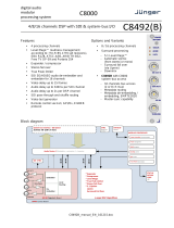
3G/HD/SD-SDI – DSP 4/8/16 audio channels
Features
• LevelMagic2™ SDI-DSP (international standards selectable) loudness control
• 4 optional 8 or 16 audio channels
• Optional surround processing
• Fail over and surround upmix
• 16 channel 3G/HD/SD-SDI de-embedder
• 16 in 16 de-embedder matrix
• 16 channel 3G/HD/SD-SDI embedder with video delay
• 32 in 16 embedder matrix
• Video test generator
• Variable audio delay of 340ms per embedder channel
• True peak brick wall limiters -20 …. 0dBTP threshold
• Remote control via web server of C8702 Frame Controller, GPI/O, EmBER plus protocol
Block diagram
C8491 Carrier Board
SYNC
System sync
inertface
MODULE CONTROLLER
CAN-BUS
interface
Audio Router / Metadata – extractor / – inserter
GPI/O
handling
Routing
control
Frame Controller
commmunication
Preset
management
Front Panel
status display
STATUS
BYPASS
LOCK
LED
DSP
control
Junger DSP Algorithms
16 Ch
16 Ch
16 Ch
16 Ch
SDI -SYNC
* Expander
* Compressor
* Level Magic
* True Peak Limiter
* Stereo Fail Over
* 5.1 Option
Upmix
Surround Fail Over
SDI OUT 2
THROUGH
SDI IN
SDI OUT 1
Embedder
De-
Embedder
Local
Routing
Relay Bypass
SDI 50 Piggyback Board
SDI OUT 2

digital audio
modular
processing system
C8000
3G/HD/SD-SDI – DSP 4/8/16 audio channels
C8491
page 2/28
Technical specifications
Standards Video complies with SMPTE 424/425M (3G, Level A and B), SMPTE
292M (HD) or SMPTE 259M (SD). Automatic format detection.
Audio embedding and de-embedding complies with SMPTE 299M (3G,
HD) or SMPTE 272M-AC (SD).
Metadata embedding and de-embedding complies with SMPTE 2020-2.
Video Data Rate 2970/296Mbps (3G), 1485/1483.5Mbps (HD), 270Mbps (SD)
Video Formats 1080p23.975, 24, 25, 29.97, 30, 50, 59.94, 60
1080i50, 59.94, 60
720p23.975, 24, 25, 29.97, 30, 50, 59.94, 60
625i50, 525i59.94, …
Video Delay User selectable 0 …15frames, can be disabled
Audio 24bits, transparent forwarding of PCM and compressed audio (SDI)
40bits floating point processing (DSP)
Audio Channels SDI: 16 inputs and 16 outputs (4 groups with 4 channels each)
DSP: 16 inputs and 16 outputs
Audio Sample Rate 48kHz (SDI compliant)
Audio Delay Embedder audio delay selectable 0 … 340ms per channel
DSP audio delay selectable 0 … 2s per channel
Impedance 75Ohm
Return loss > 15dB, 5 … 1485MHz
> 10dB, 1485 … 2970MHz
Cable length (max.) 250m @ SD for Belden 1694A cable
230m @ HD for Belden 1694A cable
140m @ 3G for Belden 1694A cable
BNC Input
Jitter tolerance > 0.7UI (Alignment)
Impedance 75Ohm
Output voltage 0.8Vpp (typ.)
Return loss > 15dB, 5 … 1485MHz
> 10dB, 1485 … 2970MHz
BNC Output
Output jitter < 0.2UI (Alignment), < 0.5UI (Timing)
Video Latency Input to Output 120 … 200pixel, depends on video standard
Audio Latency
(SDI) Input to Output Embedder and de-embedder combined
HD, 3G < 0.6ms
SD typ. 1.5ms (< 2ms)

digital audio
modular
processing system
C8000
3G/HD/SD-SDI – DSP 4/8/16 audio channels
C8491
page 3/28
Power Supply 5Vdc (4.75 … 5.25V), max. 1.200mA
Dimension 3RU, 4HP, 160mm depth (DIN41612 backplane connector)
Environmental Operating temperature 0 … 40ºC,
Non-operating -20 … 70ºC,
Humidity < 90%, non-condensing
General Features • Power fail relay bypass (may be activated via GUI)
• Lip-Sync compensation for processed and non-processed audio
signals
• Dedicated routing for non-processed channels, all channels
can be routed to/from the device or looped through
• Test pattern generator
Location of switches:

digital audio
modular
processing system
C8000
3G/HD/SD-SDI – DSP 4/8/16 audio channels
C8491
page 4/28
Initial set up
ADDRESS: This rotary encoder sets the CAN ID of the C8491. The 16 switch positions
are hexadecimal numbers (0x0 to 0xF). The CAN address also defines the
place of the module icon within the GUI overview of rows three to six.
SW1:
#1 OFF = internal use and must be set to OFF.
#2 OFF = CAN bus speed 256kBit/s
ON = CAN bus speed 1Mbit/s
Important Note! For a certain number of modules like the C8491 it is possible to communicate with a
CAN bus speed of 1MBit/s. This provides more bandwidth to move measuring data from the module via
the frame controller to the J*AM based loudness logger. You must use J*AM version 2.9 or higher.
Be sure that all modules within a frame are operating with the same CAN bus speed.
#3 OFF = internal use and must be set to OFF.
#4 ID +16 OFF = CAN bus address range is standard (counting from 0x0 to 0xF)
see rotary encoder settings above.
ON = CAN bus address range is extended by +16
(counting from 0x10 to 0x1F)
INIT Pressing the INIT button during power up will initialize the module
parameters to factory default values.
General remark! The C8491 is a 16 channel device from the SDI de-embedding / embedding point of
view but the number of audio processing channels may be different.
Four channels are standard while 8 or 16 channels are an option. Since all parameters are the same for
each version, this document describes the 16 channel processor version. The difference will be the
number of fail over circuits (1 for the 4Ch, 2 for the 8Ch and 4 for the 16Ch option).
Another option is 5.1 surround processing. If this option is enabled one may also perform permanent
surround upmix or use the upmix for surround fail over.

digital audio
modular
processing system
C8000
3G/HD/SD-SDI – DSP 4/8/16 audio channels
C8491
page 5/28
Web browser based GUI
OVERVIEW
The modules overview of a frame (below the display of an example frame):
By simply clicking on the spanner tool symbol the control pages of the C8491 will open up as well
as the status pane on the left hand side, which is also shown when you hovering with the mouse over
the module graphics blocks.

digital audio
modular
processing system
C8000
3G/HD/SD-SDI – DSP 4/8/16 audio channels
C8491
page 6/28
STATUS PANE
The status area is quite big for the C8491 so you may face difficulties when displaying it on lower
resolution displays. You may shrink it by pressing on the little "fly foot print":
Now some information are suppressed and you are able to see the
most relevant status information without the need to put the browser
into full screen mode.
C8491 DEVICE 04
- Given name of the module (may be changed on the
DEVICE pane). It will be default set during initialization to module type
amended by the word DEVICE
and the CAN address 04 the module had at
that moment.
System name of the module and short description.
DSP Preset Name of the actual loaded preset.
Routing/SDI Preset Name of the actual loaded preset.
Failover/Upmix Preset Name of the actual loaded preset.
SDI Status [SD / HD / 3G / TG / UNLOCKED]
Soft LED: green if Rx locked.
yellow if Rx locked + async audio
if Rx unlocked + Always ON + Last Valid
red if Rx unlocked + TG=OFF or TG=AUTO
if TG=Always ON + None
BYPASS grey / red turns red if a bypass is activated.
DSP1 DSP2 if the DSP1A or DSP2 bypass
SDI SDI-Relay check box or if the SDI bypass or the
fail-over relay is activated.
Bit Transparent shows the bit transparent status of the
Ch 01/02 … 07/08 respective DSP channel pairs.
Ch 09/10 … 15/16
Failover/Upmix turns green if a function is active.
A B Upmix 1
C D Upmix 2
Processing Status turns green if observation of processing
status is enabled. Turns red if processing
status is bad (see DSP1-A Processing
Status Enable).
SDI De-Embedder Status [grey - nothing embedded
green - PCM
yellow - Dolby E / D / D+]
Temperature Module temperature measured on the
surface of the PCB.
Metering clicking on that symbol will open the applet
to display meter bar graphs (see page 24
for an example) channels.

digital audio
modular
processing system
C8000
3G/HD/SD-SDI – DSP 4/8/16 audio channels
C8491
page 7/28
Front panel Status LEDs color code
off green flashing green red flashing red
STATUS never OK OK, GUI access boot error boot error,
GUI access
BYPASS if STATUS
= red at least one
program active,
no SDI / relay
bypass
all programs
bypass or SDI /
relay bypass
never never
LOCK never SDI locked never SDI unlock never
PRESETS

digital audio
modular
processing system
C8000
3G/HD/SD-SDI – DSP 4/8/16 audio channels
C8491
page 8/28
The C8491 has 3 banks of Presets: DSP / Roting/SDI / Failover/Upmix.
The status window on the left hand side shows the names of the active presets. The word “modified”
will appear in line with the preset name if any preset parameter was changed since loading this preset.
DSP Is dedicated to audio processing (Leveler, Compressor / Limiter /
Expander / Fail Over / Upmix).
Load Select a preset by name and press <LOAD>.
Loaded from preset The soft LEDs show the channels which will be controlled by the
active preset. The number of soft LEDs depends on the program
configuration. E.g. channels 1-6 are represented by one soft LED
because they belong to a 5.1 program while 7/8 represent a stereo
program as well as 9/10 and 11/12. Channels 13, 14, 15, 16
belong to mono programs whereas channel 15, 16 are not part of
the preset currently loaded.
Here another example where channels 15 and 16 are not part of
the actual loaded preset:
Save as # Select a preset NV memory number.
Name Assign the preset a name (up to 16 digits).
and press <SAVE>.
Channels stored The check boxes define which channels will be stored when you
in presets save a preset. The number of check boxes depends on the
program configuration.
Here an example where DSP1 (Ch 1 – 8) is set for 5.1 + 2
operating mode and DSP 2 (Ch 9 – 16) is set for 4 x 2 operating
mode. Ch 9/10 and 11/12 are linked for stereo operation and
13, 14, 15, 16 are not linked (mono mode). The parameters of
channels 15 and 16 will not be stored:
Routing/SDI controls the SDI Embedder / De-Embdder including delays and the
bus routing if the (B) option is activated.
Load Select a preset by name and press <LOAD>.
Save as # Select a preset NV memory number.
Name Assign the preset a name (up to 16 digits).
and press <SAVE>.

digital audio
modular
processing system
C8000
3G/HD/SD-SDI – DSP 4/8/16 audio channels
C8491
page 9/28
Failover/Upmix The third group (#33 … #40) is intended for fail over and upmix
parameters.
Load Select a preset by name and press <LOAD>.
Loaded from preset The soft LEDs show the Fail Over circuit(s) controlled by the preset
currently loaded:
I.e. a preset may change the parameters for one 2ch fail over
without changing the parameters for another one.
Save as # Select a preset NV memory number.
Name Assign the preset a name (up to 16 digits).
and press <SAVE>.
Processing blocks The check box(es) define from which processing block parameters
stored in preset will be stored next:
The number of processing blocks involved depend on the
operating mode for the DSPs.
Preset Clipboard <COPY TO CLIPBOARD> copies the active preset to a clip board,
the data may be used by other modules inside the same frame.
Backup Presets to File <BACKUP> creates a backup XML file which may be saved
on a PC.
Restore Presets from File <Browse… > opens a file dialog to select a previously stored
preset file. <RESTORE> will upload the file and overwrite existing
presets for this module.

digital audio
modular
processing system
C8000
3G/HD/SD-SDI – DSP 4/8/16 audio channels
C8491
page 10/28
DEVICE
INFO
Device Name You can assign the module an individual name (up to 16 digits).
Press <CHANGE NAME> to make the new name effective.
Platform [C8491-1]
Hardware platform of the module.
Parameter Version [x]
The firmware of the module undergoes revisions where parameters
may be added while others become obsolete. The parameter
version indicates it.
Important Note! It is mandatory to initialize the module to factory defaults if the parameter version has
changed in order to clean the memory from rubbish data. Otherwise you may experience malfunctions.
FIRMWARE displays the firmware versions of the C8491 components:
Controller The module controller
Bootloader The version of the boot loader
DSP The processing DSP
FPGA The routing and audio interface for the DSP
SDI The firmware of the SDI board

digital audio
modular
processing system
C8000
3G/HD/SD-SDI – DSP 4/8/16 audio channels
C8491
page 11/28
RESET
Restart Module Pressing <RESTART> performs a warm start (soft reset)
Initialize and Restore Pressing <INITIALIZE> restores the factory default values for all
Factory Defaults parameters of the module including all presets. You will lose
your presets and settings. It's highly recommended to backup the
settings and presets to a PC first.
BACKUP / RESTORE
Backup Settings and Pressing <BACKUP> will put all active parameters and the
Presets to File content of all presets into an XML file.
You may store such file on a PC.
Restore Settings and You may browse a matching XML file from a PC.
Presets from File Pressing <RESTORE> will overwrite all active parameters and the
content of the presets with the content from the backup file.
SETUP
This page shows the function blocks which are available for the respective programs. The display
depends on the program configuration of the DSPs. Below an example where
DSP 1 is configured for 5.1 + 2 whereas DSP 2 is configured for 4 x 2 program processing:

digital audio
modular
processing system
C8000
3G/HD/SD-SDI – DSP 4/8/16 audio channels
C8491
page 12/28
SDI Bypass [Off / On]
You may bypass the audio de-embedder / embedder for testing or
trouble shooting purposes.
Relay Bypass [Off / On]
The main SDI pass from SDI IN to SDI OUT 1 has a power fail
bypass relay. The relay may be turned off manually for testing or
trouble shooting purposes.
Relay Wait Time [3 … 60 seconds]
After Power Up In order to have the DSP operational and all module function
blocks up and running before processing starts you may delay the
moment of switching on the signal path by x amount of seconds.
Stream Select (3G-B) [Stream 1 / Stream 2]
For 3G-B SDI operation (see SMPTE 372 for details) you must
select which of the two streams runs through this particular
module.
SNMP: Input Lost [Off / On]
The monitoring of the physical SDI input can be disabled for the
SNMP agent to prevent unwanted traps if the module is frequently
taken out of service.
Alternative Input Due to the fact that the DSP is fed in 2Ch mode and in case of
Channel Allocation surround operation it is possible to select between the standard
TV broadcast (L / R / C / LFE / Ls / Rs) and the alternative movie
picture (L / C / R / Ls / Rs / LFE) channel allocation.
Alternative Output See above
Channel Allocation

digital audio
modular
processing system
C8000
3G/HD/SD-SDI – DSP 4/8/16 audio channels
C8491
page 13/28
Important Note! The available number of processing channels depends on the license that is enabled for
the particular module. Here is an example for the basic configuration that has four processing channels
only (no channel license is enabled):

digital audio
modular
processing system
C8000
3G/HD/SD-SDI – DSP 4/8/16 audio channels
C8491
page 14/28
DSP 1A - 4 x 2 mode
From here you can control the audio parameters of the C8491 function blocks.
For detailed explanation of the LevelMagic parameters pls. see the separate document:
Junger_Processing-Parameters_xxyyzz.pdf which you may download from our web site.
Operating Mode [5.1 + 2 / 4 x 2]
defines the number of audio channels which are used for one
audio program. All relevant processing blocks will be configured to
meet the selected mode.
Loudness Control Mode [Level / ITU BS.1770-1, -2, -3, -4 / EBU R 128 / ARIB TR-B32
ATSC A/85 (2011 7 2013) / Free TV OP-59 / Porteria 354]
Bypass [ON / OFF]
The processing parameters will be bypassed to validate the actual
settings. If enabled, the respective Bypass DSP1 or DSP2 soft
LED turns red in the status panel:

digital audio
modular
processing system
C8000
3G/HD/SD-SDI – DSP 4/8/16 audio channels
C8491
page 15/28
Link [Unlinked / Linked]
defines the coupling of the control circuits in order to maintain the
listening balance for correlated signals or to provide a grouping of
the setup parameters for multi channel signals.
Input [ON / OFF]
Input Gain [-20 … +20 dB]
Input Delay Coarse (ms) [0 … 2000]
Input Delay Fine [0 … 255]
(samples)
Leveler [ON / OFF] turns off Transient Processor as well.
Processing Profile [live / speech / pop / classic]
Loudness Target (dBFS) Level mode [0 … -50]
(LKFS) ITU mode [0 … -50]
(LUFS) EBU mode [0 … -50]
Time (s/min/h) [10, 20, 40 sec. / 1, 2, 5, 10, 20, 40 min / 1, 2 h]
Max Gain (dB) [0 … 40]
Freeze Level (dBFS) [-20 … -60]
Transient Processor
Max Gain (dB) [0 … 40]
Response [soft, mid, hard]
Limiter [ON / OFF]
Processing Profile [live, speech, pop, uni, classic]
Max True Peak (dBTP) [0.0 … -20]
Expander [ON / OFF]
Threshold (dBFS) [-60 … -20]
Range (dB) [0 …. 20, Gate]
Release Mode [0 / 1 live / 2 speech / 3 pop / 4 uni / 5 / 6 classic / 7 / 8 / 9]
Compressor [ON / OFF]
Reference Level (dBFS) [0 … -40]
Range (dB) [0 … 8 …. 20]
Ratio [1: 1.1 … 1: 4.0]
Processing [0 / 1 live / 2 speech / 3 pop / 4 uni / 5 / 6 classic / 7 / 8 / 9]

digital audio
modular
processing system
C8000
3G/HD/SD-SDI – DSP 4/8/16 audio channels
C8491
page 16/28
Proc Status Enable [ON / OFF]
If the average gain of the module is equal or above the
Leveler Max Gain for more than 10s the respective
Processing Status soft LED turns red. This status information is
condensed for all processing channels by the module controller.
The frame controller will condense the status information for all
processing modules within a frame and may generate a SNMP
trap and/or fire a GPO. In this case the SNMP manager may poll
the frame for details to “see” which processing channel sticks.
Bit Transparent [off / on]
indicates that a channel pair is in bit transparent mode
to let non audio signals pass through without the DSP processing
to maintain data structure for non audio signals.
Expert [show / don't show]
The expert mode offers the possibility for manual intervention of
the adaptive behavior of the LevelMagic process for critical
material. For details pls. see the above mentioned document.
Clear Processing History manually or GPI controlled
(Preset) [disable / enable]
defines if the switch is included in a preset. This allows clearing the
processing history if a preset is loaded.
Initial Dynamic Gain (dB) [-40 … 1 … 15]
Start value for the LevelMagic process after Clear Processing
History.
AGC Recovery [normal / fast]
Low Level Behavior
Processing Threshold [-80 … -70 … -20]
(dBFS) The threshold from where the processing gain will behave as
defined by Below Threshold Mode.
Below Threshold Mode [release, hold]
returns slowly to 0 dB gain change or stays at the Processing
Threshold.

digital audio
modular
processing system
C8000
3G/HD/SD-SDI – DSP 4/8/16 audio channels
C8491
page 17/28
DSP 1B – 4 x 2 mode
The C8491 offers the feature to use pairs of channels in a fail over mode. I.e. if the audio signal fails
in the first audio pair, the processor may switch over to the adjacent (e.g. 1/2 >> 3/4) pair
automatically. The functions of the circuits Failover A – Failover B are similar.
The switch over will be performed by a cross fade.
Failover A
Mode [Primary / Secondary / AUTO]
Selection between both inputs and the auto mode.
Dual Mono [OFF / AUTO]
If the fail over input is fed by a dual mono signal, the circuit may
automatically copy the opposite one if one fails.
Fail Threshold (dBFS) [-60 … -40]
Trigger threshold for the fail detector.
Fail Wait (s) [1.5 … 10.0]
Time from detection of an audio loss to the moment of switch over.
Fail Return (s) [0.0 … 10.0]
Time from the detection of an audio until switch back.
Side Chain Filter [ON / OFF]
A high pass filter (300 Hz) and a low pass filter (3000 Hz) are applied
to the detector side chain (not the audio path) to prevent hum and
noise from blocking fail over switching.

digital audio
modular
processing system
C8000
3G/HD/SD-SDI – DSP 4/8/16 audio channels
C8491
page 18/28
DSP 2A – 5.1 + 2 mode
As mentioned above there is also a 5.1 + 2 program configuration available if one has bought the
surround option for the C8491. In this case the first 6 channels of the DSP are linked for surround
processing. This will also apply to DSP 1 if 5.1 + 2 is selected. The example above shows a condition
where the LFE is not linked to the other surround channels and may be controlled independently.
The remaining two channels may be used for an independent stereo audio program or fro two mono
channels.
Depending on the loudness control mode, the link options are different. While ITU defines a certain
link condition for loudness control and measurement, the proprietary Junger "Level" mode allows for
more detailed link variances. The screen shot below shows the most sophisticated MOVIE mode:

digital audio
modular
processing system
C8000
3G/HD/SD-SDI – DSP 4/8/16 audio channels
C8491
page 19/28
DSP 2B – 5.1 + 2 mode
If you have bought the surround option you will get the option to do an upmix either for permanent
operation or as a fail over feature to maintain a surround image if the input surround signal disappears.
Also a downmix block is available that can be used to feed a stereo program path or it may be used as
a fail over source for the stereo path.
Beside the upmix algorithm, the upmix block has a surround detector that will decide if an input
surround signal has disappeared under certain conditions:
Fail Over C (Upmix) This can be used to provide a two stage fail over in case of upmix.
The upmix source signal can be either the incoming L/R surround pair
"Primary" or an extra two channel input "Secondary".
If the surround input is driven by an upstream Dolby E decoder and
the signal changes from decoded D-E to PCM stereo on L/R, this
stereo will for example be used as an upmix source. But it may also
be desirable that in case surround fails a different input is used as the
upmix source or the upmix is performed permanently from the
secondary input.

digital audio
modular
processing system
C8000
3G/HD/SD-SDI – DSP 4/8/16 audio channels
C8491
page 20/28
Mode [Primary / Secondary / AUTO / AUTO no Upmix]
You can select between one of the 2ch inputs and the auto mode and
auto mode with upmix disabled (e.g. for path through of
announcements).
Dual Mono [OFF / AUTO]
If the fail over input is fed by a dual mono signal, the circuit may
automatically copy the opposite one if one fails.
Fail Threshold (dBFS) [-60 … -40]
Trigger threshold for the fail detector.
Fail Wait (s) [1.5 … 10.0]
Time from detection of an audio loss to the moment of switch over.
Fail Return (s) [0.0 … 10.0]
Time from detection of an audio loss until switch back.
Side Chain Filter [ON / OFF]
A high pass filter (300 Hz) and a low pass filter (3000 Hz) is applied to
the detector side chain (not the audio path) to prevent hum and noise
from blocking fail over switching.
Surround Detect To perform an automatic upmix in case the main surround fails.
Switch [AUTO / FIX Surround / FIX Upmix]
The surround switch may be permanently [FIX] connected to the
surround input or the upmix output but it may also perform an [AUTO]
switch over in case the surround input fails.
Detection [Center / Surround / Center or Surround / Signal loss]
Here you can decide which channels must be observed for signal loss
to operate the surround switch.
Fail Threshold (dBFS) [-80 … -70 … -40]
If the RMS weighted input level drops below this value a fail signal will
be generated.
Fail Wait (s) [0.0 … 10.0]
Time from detection of an audio loss to the moment of switch over.
The return from the fail condition (in case surround comes back) will
be immediate.
Downmix
Out Gain (dB) [-20 … 0 … 20]
Center Mix Level (dB) [-12.0 … -3.0 … 0.0]
Surround Mix Level [-12.0 … -3.0 … 0.0]
(dB)
Options
Latency Compensation [OFF / ON]
Since the upmix has a certain latency (see Upmix > Processing Time)
it can be compensated automatically for the stereo pair to avoid lip
sync issues between an upmixed surround and the stereo path.
Failover D (Stereo)
Mode [Prinmary / Secondary / AUTO]
The second fail over circuit can take the downmix as a fail over source
in case the input signal fails. But it may simply put the downmix
through permanently (Mode switch is set to Secondary).
The other parameters are already described in the DSP 1B section.
/