Page is loading ...

C8087_manual_EN_150916.doc
digital audio
modular
processing system
C8000
Upmix / Fail Over
C8087
Features
•
Input format detector auto detection of mono, stereo, surround
•
Upmix input selection surround L/R or independent stereo L/R
•
Upmix modes mono, stereo, automatic
•
Surround fail over between surround input and upmix
automatic or manual / remote controlled
•
Stereo downmix from surround input
•
Stereo fail over between alternative stereo input or surround downmix
automatic or manual / remote controlled
•
8 Setup / routing presets manual (via GUI), remote controlled (GPI or Ember+)
•
8 Upmix presets manual (via GUI), remote controlled (GPI or Ember+)
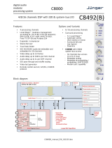
Block diagram
C8087 Carrier Board
SYNC
System sync
inertface
MODULE CONTROLLER
Input Gain
Downmix
Surround Detector
2x Fail Over
Upmix
Latency compensation
2x Limiter
Ch 1/2
CAN-BUS
interface
BACK PLANE audio interface
32 bus Lines (I/O, 2/ 8 Ch mux)
Audio router
GPI/O
handling
Frame Controller
commmunication
Preset
management
Front Panel
status display
STATUS
LED
6 Ch
Downmix Matrix / Upmix Processor / Surround Detector / Fail Over
Ch 3/4
Ch 5/6
6 Ch
Ch 7/8
Ch 1/2
Ch 3/4
Ch 5/6
Ch 7/8
Downmix
2 Ch
2 Ch
DSP control

digital audio
modular
processing system
C8000
Upmix / Fail Over
C8087
Page 2/
16
Technical data
Standards Failover and Upmix module for uncompressed multichannel audio
Audio Formats PCM (24bits)
Audio Channels 8 inputs
8 outputs
Channel Modes 3/2L and 2/0
Audio Sample Rate 48kHz
Upmix 3 … 100ms Processing Latency
Downmix
Power Supply 5Vdc (4.75 … 5.25V), max. 800mA
Dimension 3RU, 4HP, 160mm depth (DIN41612 backplane connector)
Environmental Operating temperature 0 … 40ºC
Non-operating -20 … 70ºC,
Humidity < 90%, non-condensing
General Features • Upmix of stereo or mono to 3/2L
• Downmix of 3/2L to 2/0
• Surround fail over to upmix
• Stereo fail over to downmix
• Automatic modes
• Brick wall limiters

digital audio
modular
processing system
C8000
Upmix / Fail Over
C8087
Page 3/
16
Installation
The C8087 does not have front panel controls.
It must be configured via web browser and the C8702 Frame Controller.
Above is a schematic view of the PCB. You must set these switches carefully in order not to disturb the
audio signal of other parties within a c8k frame.
The module has a front panel STATUS LED. It shows green if the module is working correctly. It turns red
if something is wrong and it flashes if the module is under remote control (in focus).
Since this type of module has an electronic output routing facility, great care must be taken when installing
or exchanging a module!
SW1
1: BUS-EN ON
The output configuration will be taken from the NV (non volatile) memory
after power up.
OFF
Will set all bus outputs to Tri-State-Mode (inactive). Now you can use the
frame controller to configure the board. This configuration will automatically
be stored into the NV memory. To enable the configuration for the next
power up you must pull out the module and set BUS-EN=ON again.
Important note! If an unknown output bus configuration is stored, it can cause a conflict with other
modules in the frame. If you are not sure about the output bus configuration you must turn BUS-EN=OFF
before inserting such a module into a system that is On Air.

digital audio
modular
processing system
C8000
Upmix / Fail Over
C8087
Page 4/
16
2: Not used OFF
3: Not used OFF
4: ID +16 OFF
CAN address ranges from 0x0 to 0xF (0 – 15)
ON
CAN address range is extended by +16, ranges from 0x10 to 0x1F (16 – 31)
SW2 Rotary encoder
CAN 0 – F
ADDR Sets the CAN bus address. Each module within a frame must be assigned a
unique CAN bus address for proper communication with other modules of
the frame (see also ID +16 above).
Important note! This address also sets the position of the module graphic when you control the frame via
the web GUI by a C8702 frame controller.
Addresses from “0” to “7” will place the module graphic into the third row
(first row shows the frame controller and sync modules, second row is
empty). Addresses “8” to “F” will place it into the fourth row and so on.
I.e. address “0” will place it in the upper left position of row 3, while “1F” will
place it in the lower right position of row 6.
SW3
INIT pressing the INIT button during power up will initialize the module parameters
to factory default values.
Status LED
On the front panel is a status LED:
STATUS green = OK
red = bad
flashing = module is in focus of the frame controller (under GUI control)

digital audio
modular
processing system
C8000
Upmix / Fail Over
C8087
Page 5/
16
Remote configuration via web interface
OVERVIEW:
Clicking on the spanner tool within the module graphics of the C8087 will open the pages of that
module.

digital audio
modular
processing system
C8000
Upmix / Fail Over
C8087
Page 6/
16
PRESETS
The 8087 has two independent banks of presets to store and recall during operation.
UPMIX SETUP
Load [1: "name" … 8: "name"]
Select a preset by number/name and press <LOAD NOW>.
The preset number and name loaded will automatically appear in
the Save as # and Name field below.
Save as # [1 … 8]
You must select a preset memory number where you would like
to save the actual parameters.
Name [16 character ASCII text]
Assign a name to the preset you are about to save here.

digital audio
modular
processing system
C8000
Upmix / Fail Over
C8087
Page 7/
16
SETUP/INPUT BUS ROUTING Refers to the SETUP pane
(FROM C8000 BUS) A bank of 8 presets to recall device settings.
Load [9: "name" … 16: "name"]
Select a preset by number/name and press <LOAD NOW>.
The preset number and name loaded will automatically appear in
the Save as # and Name field below.
Save as # [9 … 16]
Select a preset memory number where you would like to save
the actual audio program parameters.
Name [16 character ASCII text]
Assign a name to the preset you are about to save
(up to 16 digits) and press <SAVE NOW>.
Preset Clipboard Copy the active presets to a clipboard, the data may be used by
other modules inside the same frame.
Backup Presets to File Creates a backup XML file which may be stored to the PC.
Restore Presets from File You can <browse> for a backup file from the PC and restore it
by pressing the <RESTORE> soft button.

digital audio
modular
processing system
C8000
Upmix / Fail Over
C8087
Page 8/
16
STATUS DISPLAY
If you are controlling a specific module you will see a status frame on the
left hand side that also appears if you hover with the mouse over the
graphical boxes in the GUIs OVERVIEW display. If the GUI size does not
fit your screen well you may decrease the size of the status display by
clicking on the little arrows in the upper left corner to get a smaller view.
Upmix Setup Name of the actual setup preset
loaded. The word "modified" appears
as a prefix if a parameter has been
changed by the operator.
Input Bus Routing Preset Name of the actual input bus routing
preset loaded. The word "modified"
appears as a prefix if a parameter has
been changed by the operator.
Bypass Status of the Bypass switch
(see PARAMETERS page) – lights red
if bypass is on.
Surrround Channels (1 … 6)
Detect Status [Surround / Stereo / Fail]
Upmix Status [OFF / Stereo / Mono]
If upmix is enabled and upmix mode is
set to "AUTO" the soft LED lights
green.
Output Status [Through / Upmix]
Fail Over A (Upmix) [grey / green]
Output [1/2 or 7/8]
Indicates the signal source that is used
for the upmix. Lights green in auto
mode.
Dual Mono [Stereo or R/R Mono or L/L Mono]
Fail Over B (Stereo) [grey / green / yellow]
Output [Downmix or 7/8]
It can either be connected to Ch 7/8 or
to the downmix from surround input or
it can set to AUTO mode.
Dual Mono [OFF or AUTO]
Lights green if in stereo mode. Lights
yellow if in L/L or R/R mono mode.
Bus Status [grey / green / red]
Signal status of the respective input,
see SETUP pane further below.
Ch 1/2 … 7/8 [PCM / NON AUDIO / ERROR]
Bus error status Ch 1/2 … 7/8
Soft LED lights:
grey - if error detection is turned off
green - if PCM is detected
yellow - if non audio is detected
red - if an error is detected

digital audio
modular
processing system
C8000
Upmix / Fail Over
C8087
Page 9/
16
Metering Link to call the JAVA Meter Applet.
This applet is based on JAVA
technology. In order to run it,
a certified and up-to-date JAVA
version must be installed on the
PC that is used to run the
browser. The frame controller of
the c8k system holds the
certificate which Junger Audio
bought. You must check with
ORACLE that you have the
appropriate JAVA runtime
environment for your OS version
installed on your PC.
DEVICE

digital audio
modular
processing system
C8000
Upmix / Fail Over
C8087
Page 10/
16
INFO
Device Name [16 digit ASCII text]
Pressing <CHANGE NAME> will do so.
Platform [C8621]
Hardware related descriptor.
Parameter Version [x]
Software related descriptor (feature set).
FIRMWARE
Controller [xy]
Actual version of the module controller firmware.
DSP [xy]
Actual version of the metadata subsystem.
FPGA [xy]
Actual version of the system FPGA.
RESET
Restart Module <RESTART>
Pressing the soft button will warm start the module
Initialize and Restore <INITIALIZE>
Factory Defaults Pressing the soft button, will clear the parameter memory and
will initialize all parameters to their factory default values.
BACKUP / RESTORE
Backup Settings and <BACKUP>
Presets to File Pressing the soft button will create an XML file that one may
store on a PC.
Restore Settings and <RESTORE> l
Presets from File Pressing the soft button will upload a backup file that has been
selected via soft button <BROWSE> and move the previously
stored settings back to the module.

digital audio
modular
processing system
C8000
Upmix / Fail Over
C8087
Page 11/
16
SETUP Setup of the module and the audio bus routing
From C8000 System Bus
8 Ch Mux [S1 … S32]
Selection of a backplane bus that carries an eight channel multiplex. The
check boxes select which pair from the multiplex stream will feed the
respective input(s) of the DECODER.
Ch 1/2 … Ch 7/8 [S1 … S32]
Here you may select the inputs of the audio processor.
To C8000 Bus The outputs from the decoder can be assigned to the C8k audio busses.
8ch Mux You can send the 8 channels from the decoder in 8ch multiplex mode
via one audio bus line. Ch 1/2 to Ch 7/8 are multiplexed that way.
Enable Bus Driver [OFF / ON]
You can disable the output drivers by un-checking the Enable Bus Driver
check box.

digital audio
modular
processing system
C8000
Upmix / Fail Over
C8087
Page 12/
16
Important Note! The bluish labels on the bus selectors represent the signal configuration of the audio
processor. Downstream equipment must be configured to receive the correct audio channels.
Bus Error Detection [ON / OFF]
The serial audio data from the frame bus can be monitored for proper
positioning of an Error-Flag. A bad Error-Flag is an indication that
there is disturbance upstream (input signal, input module).
The Error Detection can be turned off and on in general or per input.
You will see the status on the left hand side: “Input Status”.
A grey “LED” shows that the detection is disabled. While green is OK,
red indicates an error condition.
The bus status may be presented to external monitoring systems via
SNMP. The frame controller summarizes such status information and
generates SNMP traps for the frame as an entity or may activate GPOs
(if a GPI/O module is installed). The SNMP manager may afterwards poll
the “modulesStatus” for more detailed status information per input
(see SNMP documentation for details).
PARAMETER display of general parameters and setup of functions:

digital audio
modular
processing system
C8000
Upmix / Fail Over
C8087
Page 13/
16
Junger Audio provides a new 5.1 upmix algorithm for upmixing stereo or even mono sources to
multichannel surround sound while remaining acoustically downmix compatible. This is a real-time
process which does a frequency analysis of the input signal. As known from the mathematical
theory, the longer the time for such an analysis the better the result. But this will introduce more
delay for the audio path, compared to the video. This delay, if acceptable in general, may be
compensated by the video delay of the SDI embedder.
Please note that presets created with earlier firmware version are not compatible with the new
upmix algorithm!
You may take the upmix source signal from either the surround input Ch 1/2 (1L/1R) in case it
provides stereo PCM instead of surround L/R or from input Ch 7/8 (2L/2R).
The Surround Detect circuit monitors the input channels to decide if the surround signal has
disappeared in order to do an automatic upmix if desired. But the upmix may also be forced by an
event of the system that loads a preset configuration, that turns the upmix permanently on.
Bypass [ON / OFF]
If Bypass is turned ON the following parameters will be set:
Input Gain
1L/1R/1C/1Ls/1Rs (dB) 0.0
1LFE (dB) 0.0
2L/2/R (d) 0.0
Fail Over A (Upmix)
Mode Ch 1/2
Dual Mono OFF
Surround Detect
Switch FIX Surround
Output Limiter
Limiter 1 (Surround) OFF
Limiter 2 (Stereo) OFF
Fail Over B (Stereo)
Mode Ch 7/8
Dual Mono OFF
All other parameters are left as set by the operator.
Input Gain
Input Gain [-20.0 … 0.0 … 20.0]
1L/1R/1C/1Ls/1Rs (dB)
Input Gain 1LFE (dB) [-20.0 … 0.0 … 20.0]
Input Gain 2L/2R (dB) [-20.0 … 0.0 … 20.0]

digital audio
modular
processing system
C8000
Upmix / Fail Over
C8087
Page 14/
16
Fail Over A (Upmix)
Mode [Ch 1/2 / Ch 7/8 / AUTO]
Dual Mono [OFF / AUTO]
A detector looks for the input signal. If it is a left [L] or right [R] only
it mirrors that signal to [L/L] or [R/R].
Fail Threshold (dBFS) [-80 … -60… -40]
Fail Wait (s) [1.5 … 10.0]
Fail Return (s) [0.0 … 10.0]
Side Chain Filter [OFF / ON]
A high pass filter (300Hz) and a low pass
filter (3000Hz) is applied to the detector side
chain (not the audio path) to prevent hum and
noise from blocking fail over switching.
Surround Detect This section also controls the signal flow at the surround output.
The Switch is independent from the upmix state! You are able to
feed the 1L/1R output even if the upmix is not activated either by
"Upmix Enable = Off" or by "Fail Over Upmix = AUTO"
setting of that switch. Here you can also decide which channels
must be observed to operate the surround switch
(Signal Loss = All channels are gone).
Switch [AUTO / Fix Surround / Fix Upmix]
Detection [Center / Surround / Center or Surround / Signal Loss]
Fail Threshold (dBFS) [-80 … -60 … -40]
Fail Wait [0.0 … 1.0 … 10.0]
Downmix
Out Gain (dB) [-20.0 … 0.0 … 20.0]
Center Mix Level (dB) [-12.0 … -3.0 … 0.0]
Surround Mix Level (dB) [-12.0 … -3.0 … 0.0]
Output Limiter This is the well know brick wall limiter algorithm from Junger Audio.
It is set to profile = "Uni" while the threshold is set to 0dBFS
and the look ahead time is 1ms.
Limiter 1 (Surround) [OFF / ON]
Limiter 2 (Stereo) [OFF / ON]

digital audio
modular
processing system
C8000
Upmix / Fail Over
C8087
Page 15/
16
Fail Over B (Stereo)
Mode [Ch 7/8 / Downmix / Auto]
Dual Mono [OFF / AUTO]
Fail Threshold (dBFS) [-80 … -60 … -40]
Fail Wait (s) [1.5 … 10]
Fail Return (s) [0.0 … 10.0]
Side Chain Filter [OFF / ON]
A high pass filter (300Hz) and a low pass
filter (3000Hz) is applied to the detector side
chain (not the audio path) to prevent hum and
noise from blocking fail over switching.
Upmix
Enable [OFF / ON]
Upmix Mode [Mono / Stereo / AUTO]
Profile [Front Projection / Emphasize Front / Balanced /
Emphasize Surround / Wrap Surround]
Processing Time (ms) [3 … 40 … 100]
Center Divergence [0.0 … 0.70 … 1.00]
Surround Gain (dB) [-24.0 … -6.0 … -3.0]
Surrnd Balance Stereo [0.0 … 0.50 … 1.0]
Surrnd Balance Mono [0.0 … 0.50 … 1.0]
LFE Enable [OFF / ON / Effect Gate]
LFE Gain (dB) [-20.0 … 0.0 … 20.0]
LFE Effect Gate [-20.0 … -6.0 … 0.0]
Threshold (dB)

digital audio
modular
processing system
C8000
Upmix / Fail Over
C8087
Page 16/
16
GPI/O
GPIs are useful if you want to recall settings (e.g. by loading presets) or turn functions on or off
remotely. A C8k frame can handle 127 independent virtual GPI numbers. You must assign a unique
number to the respective preset / function. Such numbers are transmitted from the brc8x Broadcast
Remote Controller or from the C8817 GPI/O interface module via the CAN bus.
If the C8087 receives such a number, it will load the respective preset or execute the function.
GPOs are meant to present status information to external devices. A C8k frame can handle 127
independent virtual GPO numbers. You must assign a unique number to the respective
preset / function. In case a preset is loaded either manually via the GUI or remotely via the
brc8x or via a GPI/O module, the assigned number will be broadcast over the CAN bus.
A GPI/O module which has that number assigned to a physical output will engage that relay or a
brc8x may turn on an assigned button tally light.
Important Note! GPOs from modules and GPIs to modules don't "see" each other.
I.e. you can't use a status GPO of module "A" to load a preset for module "B" by simply assigning
a GPO number of module "A" as a GPI number of module "B".
If this is a requirement you must involve the GPI/O conversion function of the C8817 GPI/O module
(see manual for details).
/