Page is loading ...

SLC 500 BASIC and
BASIC-T Modules
Catalog Numbers 1746-BAS and
1746-BAS-T
User Manual

Important User Information
Solid state equipment has operational characteristics differing from those of
electromechanical equipment. Safety Guidelines for the Application,
Installation and Maintenance of Solid State Controls, publication SGI-1.1,
available from your local Rockwell Automation sales office or online at
http://www.literature.rockwellautomation.com), describes some important
differences between solid state equipment and hard-wired electromechanical
devices. Because of this difference, and also because of the wide variety of
uses for solid state equipment, all persons responsible for applying this
equipment must satisfy themselves that each intended application of this
equipment is acceptable.
In no event will Rockwell Automation, Inc. be responsible or liable for
indirect or consequential damages resulting from the use or application of
this equipment.
The examples and diagrams in this manual are included solely for illustrative
purposes. Because of the many variables and requirements associated with
any particular installation, Rockwell Automation, Inc. cannot assume
responsibility or liability for actual use based on the examples and diagrams.
No patent liability is assumed by Rockwell Automation, Inc. with respect to
use of information, circuits, equipment, or software described in this manual.
Reproduction of the contents of this manual, in whole or in part, without
written permission of Rockwell Automation, Inc. is prohibited.
Throughout this manual, when necessary we use notes to make you aware of
safety considerations.
WARNING
Identifies information about practices or circumstances
that can cause an explosion in a hazardous environment,
which may lead to personal injury or death, property
damage, or economic loss.
IMPORTANT
Identifies information that is critical for successful
application and understanding of the product.
ATTENTION
Identifies information about practices or circumstances
that can lead to personal injury or death, property
damage, or economic loss. Attentions help you:
• identify a hazard.
• avoid a hazard.
• recognize the consequence.
SHOCK HAZARD
Labels may be located on or inside the equipment (for
example, drive or motor) to alert people that dangerous
voltage may be present.
BURN HAZARD
Labels may be located on or inside the equipment (for
example, drive or motor) to alert people that surfaces may
be dangerous temperatures.

Publication 1746-UM004B-EN-P - December 2005
Summary of Changes
The information below summarizes the changes to this manual since
the last printing.
To help you find new and updated information in this release of the
manual, we have included change bars as shown to the right of this
paragraph.
SLC, SLC 500, Allen-Bradley, and Rockwell Automation are trademarks of Rockwell Automation, Inc.
Trademarks not belonging to Rockwell Automation are property of their respective companies.
For See page
Updated list of related publications P-2
Updated memory module location on circuit board 2-2
Availability of 1747-M3 and 1747-M4 memory modules 3-4
Updated battery location on circuit board 3-1, C-2
Revised JW1 jumper illustration 3-2
Revised JW2 jumper illustration 3-3
Revised JW3 jumper illustration 3-4
Revised JW4 jumper illustration 3-5

Publication 1746-UM004B-EN-P - December 2005
2 Summary of Changes
Notes:

i Publication 1746-UM004B-EN-P - December 2005
Table of Contents
Preface
Who Should Use This Manual . . . . . . . . . . . . . . . . . . . . . . P-1
Purpose of This Manual. . . . . . . . . . . . . . . . . . . . . . . . . . . P-1
Related Documentation . . . . . . . . . . . . . . . . . . . . . . . . P-2
How to Use This Manual. . . . . . . . . . . . . . . . . . . . . . . . . . P-2
Terms and Abbreviations. . . . . . . . . . . . . . . . . . . . . . . . . . P-3
Conventions Used in This Manual . . . . . . . . . . . . . . . . . . . P-3
Chapter 1
Module and Development
Software Overview
Overview . . . . . . . . . . . . . . . . . . . . . . . . . . . . . . . . . . . . . 1-1
BASIC and BASIC-T Modules. . . . . . . . . . . . . . . . . . . . . . . 1-2
Hardware Features. . . . . . . . . . . . . . . . . . . . . . . . . . . . 1-2
Software Features. . . . . . . . . . . . . . . . . . . . . . . . . . . . . 1-3
Module Communication Ports. . . . . . . . . . . . . . . . . . . . 1-3
Module LED Indicators. . . . . . . . . . . . . . . . . . . . . . . . . 1-4
BASIC Development Software (1747-PBASE) . . . . . . . . . . . 1-5
Typical Configurations. . . . . . . . . . . . . . . . . . . . . . . . . . . . 1-6
Module Integration . . . . . . . . . . . . . . . . . . . . . . . . . . . 1-6
Module Programming Interface. . . . . . . . . . . . . . . . . . . 1-7
Module Network Configurations . . . . . . . . . . . . . . . . . 1-10
Chapter 2
Component Selection
Memory Requirements for BASIC Programming . . . . . . . . . 2-1
Optional Memory Module . . . . . . . . . . . . . . . . . . . . . . . . . 2-2
Components Required for DH485 Communication . . . . . . . 2-3
Alternate Connection . . . . . . . . . . . . . . . . . . . . . . . . . . 2-4
1747-AIC Isolated Link Coupler . . . . . . . . . . . . . . . . . . 2-5
1747-PIC Interface/Converter . . . . . . . . . . . . . . . . . . . . 2-5
DH485 Cable Requirements. . . . . . . . . . . . . . . . . . . . . . . . 2-6
Components Required for DF1 Communication . . . . . . . . . 2-6
Chapter 3
Install and Wire Your Module
Set Module Jumpers . . . . . . . . . . . . . . . . . . . . . . . . . . . . . 3-1
Set Jumper JW1 . . . . . . . . . . . . . . . . . . . . . . . . . . . . . . 3-2
Set Jumper JW2 . . . . . . . . . . . . . . . . . . . . . . . . . . . . . . 3-3
Set Jumper JW3 . . . . . . . . . . . . . . . . . . . . . . . . . . . . . . 3-4
Set Jumper JW4 . . . . . . . . . . . . . . . . . . . . . . . . . . . . . . 3-5
Install Your module . . . . . . . . . . . . . . . . . . . . . . . . . . . . . 3-6
Wire Your Communication Ports . . . . . . . . . . . . . . . . . . . . 3-9
Wire to Ports PRT1 and PRT2 . . . . . . . . . . . . . . . . . . . . . . 3-9
Hardware Handshaking . . . . . . . . . . . . . . . . . . . . . . . . 3-10
DTE and DCE Overview. . . . . . . . . . . . . . . . . . . . . . . . 3-11
DTE - Data Terminal Equipment. . . . . . . . . . . . . . . . . . 3-11
DCE - Data Communication Equipment . . . . . . . . . . . . 3-12
Wire to Port DH485 . . . . . . . . . . . . . . . . . . . . . . . . . . . 3-14

Publication 1746-UM004B-EN-P - December 2005
ii Table of Contents
Chapter 4
Programming Overview
Understand Module Memory Organization . . . . . . . . . . . . . 4-1
Allocate SLC memory for the Module . . . . . . . . . . . . . . . . . 4-2
Module ID Codes. . . . . . . . . . . . . . . . . . . . . . . . . . . . . 4-3
BASIC Programming Instructions . . . . . . . . . . . . . . . . . . . . 4-3
BASIC Commands . . . . . . . . . . . . . . . . . . . . . . . . . . . . 4-4
BASIC Statements. . . . . . . . . . . . . . . . . . . . . . . . . . . . . 4-5
BASIC Operators . . . . . . . . . . . . . . . . . . . . . . . . . . . . . 4-6
Create and Edit a BASIC Program . . . . . . . . . . . . . . . . . . . 4-8
Enter a BASIC Program Using an ASCII Terminal. . . . . . 4-8
Run a BASIC Program . . . . . . . . . . . . . . . . . . . . . . . . . 4-10
Stop a BASIC Program . . . . . . . . . . . . . . . . . . . . . . . . . 4-11
Edit a BASIC Program Line Through an ASCII Terminal . 4-11
Delete a BASIC Program Line . . . . . . . . . . . . . . . . . . . . 4-13
Renumber a BASIC Program. . . . . . . . . . . . . . . . . . . . . 4-13
Transfer Data . . . . . . . . . . . . . . . . . . . . . . . . . . . . . . . . . . 4-14
Transfer Data Between the SLC Processor and
Port PRT2 . . . . . . . . . . . . . . . . . . . . . . . . . . . . . . . . . . 4-14
Transfer Data Between the SLC Processor and
Port PRT1 . . . . . . . . . . . . . . . . . . . . . . . . . . . . . . . . . . 4-16
Transfer Data Between the SLC Processor and
Port DH485 . . . . . . . . . . . . . . . . . . . . . . . . . . . . . . . . . 4-17
Transfer Data Between the SLC Processor and the
Module . . . . . . . . . . . . . . . . . . . . . . . . . . . . . . . . . . . . 4-19
Status Information for the SLC Processor. . . . . . . . . . . . 4-19
SLC Fault Codes . . . . . . . . . . . . . . . . . . . . . . . . . . . . . . . . 4-21
Appendix A
Specifications
Module Hardware Specifications . . . . . . . . . . . . . . . . . . . . 1-1
1747-PBASE BASIC Development Software Specifications . . 1-3
Related Products . . . . . . . . . . . . . . . . . . . . . . . . . . . . . . . . 1-3
Appendix B
Worksheets
Module Configuration . . . . . . . . . . . . . . . . . . . . . . . . . . . . B-1
What to Do Next . . . . . . . . . . . . . . . . . . . . . . . . . . . . . B-2
Port PRT1 Configuration (Jumper JW1) . . . . . . . . . . . . . . . B-2
What to Do Next . . . . . . . . . . . . . . . . . . . . . . . . . . . . . B-2
Port PRT2 Configuration (Jumper JW2) . . . . . . . . . . . . . . . B-3
What to Do Next . . . . . . . . . . . . . . . . . . . . . . . . . . . . . B-3
Optional Memory Module Selection (Jumper JW3) . . . . . . . B-4
What to Do Next . . . . . . . . . . . . . . . . . . . . . . . . . . . . . B-4
Program Port and Protocol Selection (Jumper JW4) . . . . . . B-5
What to Do Next . . . . . . . . . . . . . . . . . . . . . . . . . . . . . B-5

Publication 1746-UM004B-EN-P - December 2005
Table of Contents iii
Appendix C
Lithium Battery Replacement,
Handling, and Disposal
Battery Replacement . . . . . . . . . . . . . . . . . . . . . . . . . . . . . C-1
Battery Handling. . . . . . . . . . . . . . . . . . . . . . . . . . . . . . . . C-3
Storage . . . . . . . . . . . . . . . . . . . . . . . . . . . . . . . . . . . . C-3
Transportation . . . . . . . . . . . . . . . . . . . . . . . . . . . . . . . C-3
Battery Disposal . . . . . . . . . . . . . . . . . . . . . . . . . . . . . . . . C-5
Index

Publication 1746-UM004B-EN-P - December 2005
iv Table of Contents

1 Publication 1746-UM004B-EN-P - December 2005
Preface
Read this preface to familiarize yourself with the rest of the manual.
This preface covers the following topics.
• Who should use this manual
• The purpose of this manual
• How to use this manual
• Terms and abbreviations
• Conventions used in this manual
Who Should Use This
Manual
Use this manual if you are responsible for designing, installing,
programming, or troubleshooting control systems that use SLC 500
programmable controllers.
You should have a basic understanding of electrical circuitry and
familiarity with relay logic. If you do not, obtain the proper training
before using this product.
Purpose of This Manual
This manual is a reference guide for the design and installation of the
SLC 500 BASIC and BASIC-T modules. It describes the procedures for
installing and using the modules.
Chapter Title Contents
Preface Describes the purpose, background, and scope of this
manual. Also lists related publications.
1 Module and
Development
Software Overview
Explains the hardware and software features.
2 Component Selection Explains and illustrates how to select memory modules,
network configurations, and modems for your
application.
3 Install and Wire your
Module
Provides installation procedures and wiring guidelines.
4 Programming
Overview
Provides information needed to program your module.
Appendix A Specifications Presents the modules’ specifications.
Appendix B Worksheets Describes how to set the module for proper functioning.
Appendix C Lithium Battery
Replacement,
Handling, and
Disposal
Provides important information for the replacement,
handling, and disposal of lithium batteries.

Publication 1746-UM004B-EN-P - December 2005
2 Preface
Related Documentation
The following documents contain additional information regarding
Rockwell Automation products.
If you would like a manual, you can:
• download a free electronic version from the internet at
www.literature.rockwellautomation.com.
• purchase a printed manual by contacting your local distributor
or Rockwell Automation representative.
How to Use This Manual
To use this manual effectively, use the worksheets provided in
Appendix B. The worksheets can help you document your application
and settings and also facilitate the flow of information to other
individuals in your organization for implementation.
For Read Publication Number
A BASIC language reference manual that describes BASIC
commands, CALLS, and functions
BASIC Language Reference Manual 1746-RM001
A programming manual with detailed instructions on installing and
using BASIC development software to program the BASIC and
BASIC-T module.
BASIC Development Software
Programming Manual
1746-PM001
An overview of the SLC 500 family of products SLC 500 System Overview 1747-SO001
A description of how to install and use a Modular SLC 500
processor
Modular Hardware Style Installation
and Operation Manual
1747-UM011
A reference manual that contains status file data and instruction
set information for SLC 500 controllers
SLC 500 Instruction Set Reference
Manual
1747-RM001
A description of how to install and use a module that acts as a
bridge between DH485 networks and devices requiring DF1
protocol.
DH485/RS-232C Interface Module
User’s Manual
1747-UM005
In-depth information on grounding and wiring Allen-Bradley
programmable controllers
Allen-Bradley Programmable
Controller Grounding and Wiring
Guidelines
1770-4.1
A glossary of industrial automation terms and abbreviations Allen-Bradley Industrial Automation
Glossary
AG-7.1
An article on wire sizes and types for grounding electrical
equipment
National Electric Code Published by the National
Fire Protection Association
of Boston, MA

Publication 1746-UM004B-EN-P - December 2005
Preface 3
Terms and Abbreviations
The following terms and abbreviations are specific to this product. For
a complete listing of Allen-Bradley terminology, refer to the
Allen-Bradley Industrial Automation Glossary, publication ICCG-7.1.
• Module - SLC 500 BASIC and BASIC-T modules (catalog
numbers 1746-BAS and 1746-BAS-T)
• BASIC development software - BASIC Development Software
(catalog number 1747-PBASE)
• DH485 - network communication protocol
• EPROM - Erasable Programmable Read Only Memory
• MTOP - system control value that holds the last valid memory
address
• RS-232/423 - serial communication interface
• RS-422 - differential communication interface
• RS-485 - network communication interface
• SLC 500 - SLC 500 fixed and modular controller
Conventions Used in This
Manual
The following conventions are used throughout this manual.
• Bulleted lists such as this one provide information, not
procedural steps.
• Numbered lists provide sequential steps or hierarchical
information.
• Bold type is used for emphasis.
• Text in this font indicates words or phrases you should type.

Publication 1746-UM004B-EN-P - December 2005
4 Preface

1 Publication 1746-UM004B-EN-P - December 2005
Chapter
1
Module and Development Software Overview
This chapter introduces you to the SLC 500 BASIC and BASIC-T
modules and the BASIC development software. After reading this
chapter you should be familiar with the:
• module components and features.
• BASIC development software features.
• typical configurations of the module.
• module hardware specifications.
• module-related products.
Overview
The module and the development software provide the following
benefits.
• Easy data collection from user devices
• Integrated program debugging environment
• Operator interface capabilities
• Flexible program and data storage options
• High-level math
• Clock/calendar
• High-level programming environment
• Extensive online help system
• Easy access to editor functions through user interface
• Advanced text editor windows
TIP
The 1746-BAS-T module is a higher-speed version of
the 1746-BAS module with identical hardware
features. The modules can be interchanged, except
that the 1746-BAS-T module uses different (optional)
memory modules. Due to the high speed of the
1746-BAS-T module, existing programs written for
the 1746-BAS module may require adjustment for
identical operation using the faster 1746-BAS-T
module.

Publication 1746-UM004B-EN-P - December 2005
1-2 Module and Development Software Overview
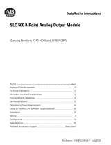
BASIC and BASIC-T
Modules
The modules are single-slot modules that reside in a SLC 500 fixed or
modular controller chassis. Use the module as
:
• a foreign device interface.
• an operator interface.
Figure 1.1 Module with Door Open
Hardware Features
The module provides the following hardware features.
• 24 KB of battery backed RAM for storage of user programs and
data
• Capacitive backup of RAM during battery change
• Socket for a standard 1747-M1, M2, M3, or M4 memory module
(1746-BAS module) for nonvolatile storage of user programs
• Socket for a 1771-DBMEM1 or -DBMEM2 memory module
(1746-BAS-T module) for nonvolatile storage of user programs
• Battery-backed, 24-hour clock/calendar
• Free-running clock with 5 ms resolution
• Two isolated 9-pin D-shell serial ports (PRT1 and PRT2) that
provide RS-232/423, RS-422, and RS-485 communication with
I/O devices
• One PRT2 port provides DF1 full-duplex or half-duplex slave
protocol for SCADA applications
• One RJ-45 port (DH485) that provides communication over the
DH485 network
• Multiple LED indicators for operator interface
• SLC 500 backplane interface
PR T1
5
4
3
2
1
9
8
7
6
PR T2
5
4
3
2
1
9
8
7
6
DH485
BASIC
PR T1
5
4
3
2
1
9
8
7
6
PR T2
5
4
3
2
1
9
8
7
6
DH485
BASIC-T

Publication 1746-UM004B-EN-P - December 2005
Module and Development Software Overview 1-3
Software Features
The module provides the following software features.
• BASIC programming with the Intel BASIC-52 language and
enhancements
• SLC 500 backplane data read and write support including image
table transfers and M0 and M1 file transfers
• Execution of programs from memory modules
• String manipulation support
• DH485 network support
• DF1 protocol support
• Full set of trigonometric function instructions
• Floating point calculations and conversion
• Extensive call libraries
Module Communication Ports
There are three communication ports on the front of the module. The
location, name, and pin numbers of these ports are listed on the
inside of the module door. They are:
• PRT1 - Used to interface the module with user devices. This port
is a serial port that accommodates RS-232/423, RS-422, and
RS-485 communication modes. Port PRT1 is capable of operating
full-duplex at 300, 600, 1200, 2400, 4800, 9600, and 19200 Kbps.
The default settings are 1200 Kbps, RS-232/423 communications.
• PRT2 - Used to interface the module with user devices or a
modem using DF1 protocol. This port is a serial port that
accommodates RS-232/423, RS-422, and RS-485 communication
modes. Port PRT2 is capable of operating full-duplex at 300, 600,
1200, 2400, 4800, 9600, and 19200 Kbps.
• DH485 - Used to interface the module with the DH485 network.
This port is not isolated and cannot directly drive the DH485
network. You must use a 1747-AIC link coupler to link port
DH485 with the DH485 network.
IMPORTANT
When DF1 protocol is selected on port PRT2, DH485
communications are disabled.

Publication 1746-UM004B-EN-P - December 2005
1-4 Module and Development Software Overview
Module LED Indicators
There are eight LED indicators on the front of the module. These LED
indicators are used for module diagnostics and operator interface.
Figure 1.2 Module LEDs
ACT
485
PR T1
PR T2
FAULT
BA LOW
LED1
LED2
BASIC
LED Color Status Indication
ACT Green ON The module is receiving power from the backplane and is
executing BASIC code.
Blinking The module is in Command mode.
OFF The module is not receiving power from the backplane. A
fault condition exists.
485 Green ON Port DH485 on the module is active for communication.
OFF Port DH485 on the module is not active for communication.
PRT1 Green Blinking Port PRT1 on the module is transmitting or receiving signals.
OFF Port PRT1 on the module is not transmitting or receiving
signals.
PRT2 Green Blinking Port PRT2 on the module is transmitting or receiving signals.
OFF Port PRT2 on the module is not transmitting or receiving
signals.
FAULT Red ON A system problem was detected during background
diagnostics. Contact your local Allen-Bradley representative.
OFF No system problems are detected during background
diagnostics.
BA LOW Red ON The voltage of the battery that backs up RAM is low. A new
battery is needed.
OFF The voltage of the battery that backs up RAM is at an
acceptable level.
LED1 Amber ON User definable. LED activated through the user program.
OFF User definable. LED deactivated through the user program.
LED2 Amber ON User definable. LED activated through the user program.
OFF User definable. LED deactivated through the user program.

Publication 1746-UM004B-EN-P - December 2005
Module and Development Software Overview 1-5
BASIC Development
Software (1747-PBASE)
The BASIC development software provides the user with a structured
and efficient means to create BASIC programs for the module. This
software is loaded into a an MS-DOS compatible personal computer. It
uses the personal computer to facilitate editing, compiling
(translating), uploading, and downloading of BASIC programs.
The BASIC development software has a menu-driven, window-type
environment that offers:
• pull-down menus to access all editor functions.
• function key access to frequently used functions.
• multiple window editing.
• cut and paste support between windows.
• search and replace support.
• search between files support.
• built-in calculator that can paste results into your program.
• ASCII look-up table.
• line draw editor to create operator interface images without
having to enter ASCII characters.
• keystroke macros.
• undo and redo functions.
• extensive help messages for each menu, menu option, and for
keywords embedded in the menu text.
• capability to create user-defined macro libraries.
• sophisticated debug tools including watch windows, single-step
operation, and go to cursor breakpoint operation.
• syntax checked translations to native BASIC to reduce debug
time.
• BASIC translator that steps through the BASIC program and
identifies errors.
• ASCII terminal mode.
• hex file transfer support.
The development software enables you to program the module from a
personal computer connected to either the module’s DH485 or PRT1
ports. The software allows direct access to the module through
terminal emulation over an RS-232/423 or DH485 network.
Refer to the BASIC Development Software Programming Manual,
publication 1746-PM001, for additional information on the software.

Publication 1746-UM004B-EN-P - December 2005
1-6 Module and Development Software Overview
Typical Configurations
The typical configuration of the SLC system that incorporates your
BASIC or BASIC-T module depends on whether the module is:
• integrated with a SLC 500 fixed or modular controller.
• programmed directly with an ASCII terminal or programmed
using a personal computer with the BASIC development
software, 1747-PBASE.
• communicating with a DH485 network or with an external
source through a modem using DF1 protocol.
Module Integration
The module is a single-slot module that is inserted into a slot in the
expansion chassis of your SLC 500 fixed controller or an open slot in
the 1746 I/O chassis of your SLC 500 modular controller. The module
may be inserted in any slot of the 1746 I/O chassis except the first slot
of the first chassis, which is reserved for the SLC modular processor.
Typical SLC fixed and modular configurations are shown in the
following figures.

Publication 1746-UM004B-EN-P - December 2005
Module and Development Software Overview 1-7
Figure 1.3 Typical Configurations
Module Programming Interface
Your module can be programmed using an ASCII terminal with ASCII
terminal emulation software. You can also use a personal computer
with the BASIC development software (catalog number 1747-PBASE).
Use an ASCII terminal to enter a BASIC program one line at a time to
the module. Use a personal computer with the BASIC development
software to create a BASIC program that is then downloaded to your
module. Typical programming interface configurations include:
• ASCII terminal interface - Figure 1.4.
• BASIC development software interface (RS-232) - Figure 1.5.
• BASIC development software interface (DH485) - Figure 1.6.
SLC 500 Fixed Controller
Slot
Filler
BASIC
or
BASIC-T
Module
Power Supply SLC 500
Modular
Processor
Input
Module
Output
Module
BASIC
or
BASIC-T
Module

Publication 1746-UM004B-EN-P - December 2005
1-8 Module and Development Software Overview
ASCII Terminal Interface
Use an ASCII terminal to enter a BASIC program one line at a time to
your module through port PRT1. The ASCII terminal connected to the
module must be an industrial terminal, workstation, or personal
computer (without the BASIC development software) that
communicates in alphanumeric mode. An ASCII terminal can also be
used to display charts or graphs generated by the BASIC program.
Figure 1.4 shows a typical ASCII terminal interface.
Figure 1.4 Module ASCII Terminal Interface
In this configuration, the RS232 port on the back of your industrial
terminal or personal computer is connected to port PRT1 on your
module. Port PRT1 must be configured as the program port.
See Chapter 3 for additional information on port configuration.
BASIC Development Software Interface (RS232)
Use a personal computer with the BASIC development software
(PBASE) to create a BASIC program that is then downloaded to your
module. PBASE provides an efficient means to edit, compile
(translate), upload, and download BASIC programs. Refer to the
BASIC Development Software Programming Manual, publication
1746-PM001, for additional information on this software.
ASCII Terminal or Personal
Computer Running ASCII
Terminal Emulation Software
Null Modem
Cable
SLC 500 Controller with BASIC or BASIC-T Module
/