Energy Suspension 3.1127G3.1127G Operating instructions
- Type
- Operating instructions

17328
7/25/00 JL
1131 VIA CALLEJON, SAN CLEMENTE, CA 92673
2000 Energy Suspension. All rights reserved. 2000 Energy Suspension. All rights reserved.
CC
May not be reproduced, in any form, or by any means,
without the written consent of Energy Suspension.
May not be reproduced, in any form, or by any means,
without the written consent of Energy Suspension.
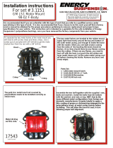
ENERGY SUSPENSION recommends
replacing both left and right side mounts
at the same time. Use set # 3-1116 for
right side mount. Use a new lock nut at
the engine bracket cross bolt location.
ENERGY SUSPENSION recommends
replacing both left and right side mounts
at the same time. Use set # 3-1116 for
right side mount. Use a new lock nut at
the engine bracket cross bolt location.
Raise vehicle to suitable height and support properly to allow easy access to the engine mounting locations. NOTE: BE
SURE VEHICLE IS SECURELY SUPPORTED BEFORE GOING UNDERNEATH. Before loosening the motor mount bolts, find a
suitable jacking location near the front of the engine block. Do not lift on crankshaft pulleys or oil pan. Severe damage
could occur to these components. If available, use an engine hoist to raise engine. Raise the engine to a height
necessary to remove load from the engine mounts. Remove the 6" long engine mounting bolt. Raise the engine again to
allow enough clearance between the engine mounting bracket and motor mount. NOTE: BE CAREFUL NOT TO CAUSE
DAMAGE TO OTHER ENGINE COMPONENTS BY RAISING THE ENGINE TOO HIGH, ie, DISTRIBUTOR CAP ON FIREWALL, FAN, etc.
Remove bolts securing motor mount to engine block. Remove motor mount from the vehicle and inspect the metal shells
for damage. NOTE: IT IS VERY IMPORTANT THAT THE METAL SHELLS BE UNDAMAGED.
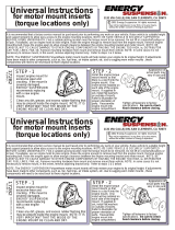
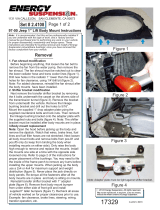
STEP - 1STEP - 1
Use a 3/8" drill bit to drill out the
two formed rivets and 1/4" drill bit
on the three hot revits. Drill down
just enough to remove rivet
material to allow the metal shells
to be separated. After separation,
remove rivets and any burrs or
sharp edges from the drilled out
holes. Use a 1/2" drill bit to drill out
the two formed rivet holes in the
bottom metal shell only.
Clean any dirt and grease that may have
accumulated inside the metal shells. NOTE: IT IS VERY
IMPORTANT THAT THE INSIDE OF THE METAL SHELLS BE
CLEAN. At this point, it is your option to have your
metal painted, powder coated, or chromed.
Clean any dirt and grease that may have
accumulated inside the metal shells. NOTE: IT IS VERY
IMPORTANT THAT THE INSIDE OF THE METAL SHELLS BE
CLEAN. At this point, it is your option to have your
metal painted, powder coated, or chromed.
STEP - 3STEP - 3
Place the assembly into a vise or
large clamp, leaving access to the
drilled out holes. Use enough
clamping force to hold the two metal
shells together, without permanently
deforming the metal (a slight amount
of metal bending may occur, this is
normal). To hold the assembly
together, use the three 1/4" bolts and
two 3/8" bolts provided into the drilled
holes, insert the 3/8" bolts from the
bottom, as shown. Use the locking
nuts to secure the assembly. Torque
the 1/4" locking nuts to 15 ft-lbs. and
the 3/8" locking nuts to 25 ft-lbs.
Reassemble motor mount into engine compartment, tighting
all bolts to factory specs. Install the 6" long bolt going through
the bracket on the crossmember. Torque to factory specs.
NOTE: The ENERGY SUSPENSION Polyurethane motor mount
insert will restore your engine to its original height. If
adjustments have been made to other engine components,
such as, fan shroud, fuel lines, etc. due to sagging, worn
motor mounts, these components will need to be readjusted
back to thier original locations. Also, be sure to check
hood clearance before closing.
HINT: Due to the many different metal configurations from
foreign and domestic manufacturers it maybe helpful to
apply a thin coating of grease or dishwashing detergent to
the polyurethane insert, at metal contact points before
installing. This will allow the insert to seat, in turn allowing
proper bolt alignment.
Reassemble motor mount into engine compartment, tighting
all bolts to factory specs. Install the 6" long bolt going through
the bracket on the crossmember. Torque to factory specs.
NOTE: The ENERGY SUSPENSION Polyurethane motor mount
insert will restore your engine to its original height. If
adjustments have been made to other engine components,
such as, fan shroud, fuel lines, etc. due to sagging, worn
motor mounts, these components will need to be readjusted
back to thier original locations.
HINT: Due to the many different metal configurations from
foreign and domestic manufacturers it maybe helpful to
apply a thin coating of grease or dishwashing detergent to
the polyurethane insert, at metal contact points before
installing. This will allow the insert to seat, in turn allowing
proper bolt alignment.
Also, be sure to check
hood clearance before closing.
NOTE: The 3/8" bolts have a square on them which will
"bite" on the inside of the 1/2" hole and keep them from
turning. However, it may be necessary to use locking
pliers to keep the bolt from turning while applying the
proper torque.
NOTE: The 3/8" bolts have a square on them which will
"bite" on the inside of the 1/2" hole and keep them from
turning. However, it may be necessary to use locking
pliers to keep the bolt from turning while applying the
proper torque.
Set # 3-1127
Instructions for 1993 - 97
Camaro/Firebird motor mount inserts
Set # 3-1127
Instructions for 1993 - 97
Camaro/Firebird motor mount inserts
RR
circular
shaped
recess
circular
shaped
recess
circular
shaped
circular
shaped
top metal shelltop metal shell
bottom metal shellbottom metal shell
-
 1
1

Energy Suspension 3.1127G3.1127G Operating instructions
- Type
- Operating instructions
Ask a question and I''ll find the answer in the document
Finding information in a document is now easier with AI
Related papers
-
 Energy Suspension 3.1121G3.1121G Operating instructions
-
 Energy Suspension 16.1107G16.1107G Operating instructions
-
 Energy Suspension 3.1151G3.1151G Operating instructions
-
 Energy Suspension 3.2105G3.2105G Operating instructions
-
 Energy Suspension Front or Rear Spring Bushings Installation guide
-
 Energy Suspension 9.5160G9.5160G Operating instructions
-
 Energy Suspension 2.4108G Installation guide
-
 Energy Suspension Body Cab Mount Set Installation guide
-
 Energy Suspension 4.5104G4.5104G Operating instructions
-
 Energy Suspension 1" Poly Body Lift Installation guide


Other documents
-
 Factory Five Racing Mk3 Roadster Assembly Manual
-
Factory Five Racing Mk4 Roadster Assembly Manual
-
Ridetech StreetGRIP Suspension System | 1967-1970 Mustang StreetGrip Suspension System Installation guide
-
-
-
 Era Replica Automobiles 427 ROADSTER User manual
-
Peugeot 405 User manual
-
-
-
Opel 1998 Omega Workshop Manual

