Page is loading ...

Installation instructions
For set # 3.1151
GM LS1 Motor Mount
98-02 F-Body
It is recommended that if you are unfamiliar with this type of work that you refer to a qualified service center
specializing in this type of work. It is also recommended that if you choose to do this work yourself that a factory
service manual be obtained for the proper procedures pertaining to removal, replacement and proper torque
specifications for your vehicle. This instruction set is intended as a guideline for the safe installation of Energy
Suspension’s polyurethane bushings, once you have removed the factory components from your vehicle.
1131 VIA CALLEJON, SAN CLEMENTE, CA 92673
R
2009 Energy Suspension. All rights reserved.2009 Energy Suspension. All rights reserved.
CC
May not be reproduced, in any form, or by any means,
without the written consent of Energy Suspension.
May not be reproduced, in any form, or by any means,
without the written consent of Energy Suspension.
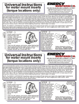
To separate the two metal halves of the motor mount you
will need to drill out two rivets and three crimps. Use a
center punch and pilot drill (1/8” drill bit) to get the rivets
started then finish the rest with a 3/8” drill bit. Rivet
Rivet
The two metal halves are bonded to the rubber mount.
Apply light heat evenly around the top and bottom of
the outer metal casing, just enough to brake the bond
with the rubber. When you see light smoke coming
from the sides of the bushing the bond should be
broken. At no time should there be any flames coming
from the rubber, if there are any flames, you need to
back off with the heat. Just push the old rubber and
inner metal sleeve out. Let the outer metal casing cool
off before cleaning the inside. Remove any burrs and
sharp edges.
Crimp Crimp Crimp
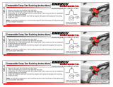
Assemble the two half together with the supplied nuts,
bolts and washers. Install the bolts from the bottom
with the washers and nuts on top. HINT: Due to the
many different metal configurations from foreign and
domestic manufacturers it maybe helpful to apply a
thin coating of grease or dishwashing detergent to the
polyurethane insert, at metal contact points before
installing. This will allow the insert to seat, in turn
allowing proper bolt alignment.
HINT: Due to the
many different metal configurations from foreign and
domestic manufacturers it maybe helpful to apply a
thin coating of grease or dishwashing detergent to the
polyurethane insert, at metal contact points before
installing. This will allow the insert to seat, in turn
allowing proper bolt alignment.
The gold zinc metal insert not covered by
polyurethane needs to be installed correctly as
shown here.
Metal sticking
out this side.
17543
12/MAY/09 BRH
Parts list:
1 - 1264 motor mount insert.
4 - 15.05.36.39 3/8-16 x 1” bolt.
4 - 15.03.69.39 flat washer.
4 - 15.07.01.40 lock nut.
/