Page is loading ...

Installation Instructions
Original Instructions
Feedback Battery Box
Catalog Number
2198-KTBT
Use these installation instructions to install or replace a battery box, install a battery, and prepare
a feedback cable for a battery box installation. The battery box requires a 3.6V, ER14252, or
equivalent, 1/2AA size battery that you supply.
Install Battery
The battery box requires a 3.6V, ER14252, or equivalent, 1/2AA size battery.
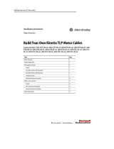
To install the battery, do the following.
1. To open the battery box, release the four snap-fit tabs.
2. Insert the battery as shown.
3. Replace the cover and check that all four snap-fit tabs are engaged.
Topic Page
Install Battery 1
Install or Replace Battery Box 2
Additional Resources 4
IMPORTANT To avoid the loss of position data, be sure to replace the battery within 10 minutes.
-
+
Snap-fit Tabs
(X4)

2 Rockwell Automation Publication 2198-IN022A-EN-P - May 2019
Feedback Battery Box
Install or Replace Battery Box
To install the battery box, follow the steps in Prepare Battery Box and continue with Install
Battery Box. To replace the battery box, follow all the steps in this section.
Prepare Battery Box
To prepare your new battery box for installation or replacement, do the following.
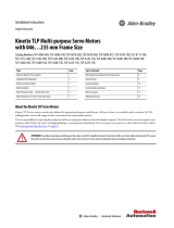
1. Release the four snap-fit tabs and remove the battery box cover.
2. Remove and save the cable clamp screw and the cable clamp.
Remove the Battery Box from the Feedback Cable
1. Release the four snap-fit tabs and remove the battery box cover.
2. Loosen the + and - terminal screws and pull out the black and red wires.
3. Remove the cable-clamp screw, cable, and the cable clamp.
Snap-fit Tabs
(X4)
Te rm in al
Screws
Snap-fit Tabs
(X4)

Rockwell Automation Publication 2198-IN022A-EN-P - May 2019 3
Feedback Battery Box
Install Battery Box
1. Position the cable clamp on the feedback cable such that the encoder battery-power wires
exit the shrink tube near the center of the battery box.
2. Place the cable in the battery box as shown and secure to the box with the supplied cable-
clamp screw.
Torque the cable-clamp screw to 0.2 N•m (1.77 lb•in)
3. Insert the wires into + and - terminals.
Torque the cable-clamp screw to a maximum of 0.35 N•m (3.098 lb•in).
4. Install the battery. See Install Battery
on page 1.
5. Replace the cover.
Terminal Wire Color
+Red
-Black

Allen-Bradley, Kinetix, Rockwell Automation, and Rockwell Software are trademarks of Rockwell Automation, Inc.
EtherNet/IP is a trademark of ODVA, Inc.
Trademarks not belonging to Rockwell Automation are property of their respective companies.
Rockwell Otomasyon Ticaret A.Ş., Kar Plaza İş Merkezi E Blok Kat:6 34752 İçerenköy, İstanbul, Tel: +90 (216) 5698400
Rockwell Automation maintains current product environmental information on its website at
http://www.rockwellautomation.com/rockwellautomation/about-us/sustainability-ethics/product-environmental-compliance.page
.
Publication 2198-IN022A-EN-P - May 2019
Copyright © 2019 Rockwell Automation, Inc. All rights reserved. Printed in the U.S.A.
Additional Resources
These documents contain additional information concerning related products from Rockwell
Automation.
You can view or download publications at http://www.rockwellautomation.com/global/
literature-library/overview.page.
Rockwell Automation Support
For technical support, visit http://www.rockwellautomation.com/support/overview.page.
Resource Description
Kinetix® Servo Drives Specifications Technical Data,
publication KNX-TD003
Provides product specifications for the Kinetix Integrated
Motion over EtherNet/IP™ network, Integrated Motion over
Sercos interface, EtherNet/IP networking, and component
servo drive families.
Kinetix Motion Accessories Specifications Technical Data,
publication KNX-TD004
Provides product specifications for Bulletin 2090 motor and
interface cables, low-profile connector kits, drive power
components, and other servo drive accessory items.
Kinetix 5100 Single-axis EtherNet/IP Servo Drives Users
Manual, publication 2198-UM004
Information on how to install, configure, start, and
troubleshoot your Kinetix 5100 servo drive system.
Industrial Automation Wiring and Grounding Guidelines,
publication 1770-4.1
Provides general guidelines for installing a Rockwell
Automation industrial system.
Product Certifications website: rok.auto/certifications
Provides declarations of conformity, certificates, and other
certification details.
/