Page is loading ...

Installation Instructions
Original Instructions
2090-Series Kinetix TLP Power and Feedback Cables
Catalog Numbers 2090-CTPW-MEDF, 2090-CTPW-MDDF, 2090-CTPB-MDDF, 2090-CTPW-MCDF, 2090-CTPB-MCDF, 2090-CTPB-MADF,
2090-CTPW-MADF, 2090-CTBK-MBDF, 2090-CTFB-MADD, 2090-CTFB-MFDD, 2090-CTPW-MEET, 2090-CTPW-MDET, 2090-CTPB-MDET,
2090-CTPW-MCET, 2090-CTPB-MCET, 2090-CTPW-MAET, 2090-CTPB-MAET, 2090-CTBK-MBET, 2090-CTFB-MFET, 2090-CTFB-MAET
Topic Page
Before You Begin 2
Catalog Number Explanation 3
Motor Connector/Cable Compatibility 3
Install Kinetix TLP Motor Cables 5
Install Continuous-flex Extension Cables 7
Pinout Specifications 9
Additional Resources 11

2 Rockwell Automation Publication 2090-IN046A-EN-P - December 2019
2090-Series Kinetix TLP Power and Feedback Cables
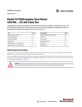
Before You Begin
Remove all packing material from within and around the item. After unpacking, verify the catalog number against the purchase order and visually
inspect the cable and each connector for damage. If necessary, notify the carrier of any shipping damage immediately.
Cables are stored and shipped in a coil. Cables retain this shape until you straighten the cable. To straighten a cable, hang a short cable from its mid-
point or lay a long cable on the floor in a straight line. Any coiling that remains in the cable is straightened out within the next 24 hours. This
practice makes the cable easier to install.
ATTENTION: Observe the following precautions when installing cables in a servo system. Failure to observe these safety notices can result in personal injury or
damage to the motor and equipment.
• Arcing or unexpected motion can occur if the power/brake or feedback cables are connected or disconnected while power is applied to the drive. Always
remove power to the servo drive before connecting or disconnecting cables at the drive or at the motor.
• To avoid electrical shock, make sure that shielded power cables are grounded at a minimum of one point. To prevent the build-up of electrical energy, factory-
supplied power cables use one of these grounding techniques:
– The overall shield is bonded to the connector housing.
– A section of the overall shield is exposed for connection to ground.
– The overall shield is connected to a ground wire.
If the exposed cable braid or a ground wire is present, connect it to the power cable clamp, housing, or another suitable chassis ground on the drive.
• The maximum cable length between the drive and the motor varies, depending on the application, but never exceeds 50 m (164 ft) for Kinetix® 5100 drives,
See Kinetix Servo Drives Specifications, publication KNX-TD003
, for additional information.
• Do not tightly gather or coil the excess length of a power cable. Heat is generated within a cable whenever power is applied. Always position a power cable so
it can freely dissipate heat.
– Do not coil a power cable except for temporary use when building or testing a machine. If you temporarily coil a power cable, you must also derate the
cable to meet local code or follow an authoritative directive, such as Engineering Section 310.15(C) of the NEC Handbook.
• The examples in this publication show all available connections. Some connections are not used for specific installations. See your drive installation
instructions or user manual for recommended wire trim lengths and wiring examples for your drive and motor application.
– Do not connect unused wires. Trim and finish unused wires to prevent accidental contact with other wires or wire shields, or with a ground connection.
IMPORTANT Standard (non-flex) cables can be bent or reformed during installation and maintenance. Continuous-flex cables can be flexed repeatedly within a specified
bend radius when properly installed.
Do not use standard cables in a continuous-flex operation.

Rockwell Automation Publication 2090-IN046A-EN-P - December 2019 3
2090-Series Kinetix TLP Power and Feedback Cables
Catalog Number Explanation
Catalog numbers consist of various characters, each of which identifies a specific option. Use the catalog numbering chart
below to understand the configuration of your Kinetix TLP cable.
Motor Connector/Cable Compatibility
TLP-A046…TLP-A100 servo motors are equipped with rectangular connectors.
2090 - C T xx - xx xx - xx x xx
Cable Length
See the Technical Specifications in the Kinetix Motion Accessories Specifications Technical Data, publication KNX-TD004.
Wire Gauge Size (PB, PW, and BK cable types)
20, 18, 16, 14, 12,10, 08, 06, and 04 AWG
Cable Type
PB = Motor power with brake wires
PW = Motor power only
FB = Motor feedback
BK = Motor brake
Cable Type
A = Standard, non-flex
F = Continuous-flex
Accessory Component
C = Cable
Drive-end Connector Type
DF = Flying-lead power and brake cable
DD = Premolded connector on feedback cable
ET = Extension receptacle on power, feedback, and brake cables
Motor-end Connector Type (PB and PW cable type)
MA = Rectangular, applies to TLP-A046, TLP-A070, TLP-A090, and TLP-A100 motors
MC = Military style, applies to TLP-A115-xxx and TLP-A145-xxx motors
MD = Military style, applies to TLP-A200-200, TLP-A200-300, TLP-A200-350, and TLP-A200-450 motors
ME = Military style, applies to TLP-A200-550, and TLP-A200-750 and TLP-A235-xxx motors
Matching Motor Family
T = Compatible with Kinetix TLP servo motors
Motor-end Connector Type (FB cable type)
MA = Rectangular, applies to TLP-A046, TLP-A070, TLP-A090, and TLP-A100 motors
MF = Military style, applies to TLP-A115, TLP-A145, TLP-A200, and TLP-A235 motors
Motor-end Connector Type (BK cable type)
MB = Military style, applies to TLP-A200-550, and TLP-A200-750 and TLP-A235-xxx motors
Encoder Type (FB cable types)
CF = Serial absolute, battery backup
Bulletin Number
1
2
6
5
4
3
1
2
6
5
4
3
9
8
7
• TLP-A046-xxx…TLP-A100-xxx motors
• Receives rectangular cable plugs
• 2090-CTPB-MADF-xxAxx (standard, non-flex) power/brake cables
• 2090-CTPB-MADF-xxFxx (continuous-flex) power/brake cables
• 2090-CTPW-MADF-xxAxx (standard, non-flex) power-only cables
• 2090-CTPW-MADF-xxFxx (continuous-flex) power-only cables
• 2090-CTFB-MADD-CFAxx (standard, non-flex) drive-end connector feedback cables
• 2090-CTFB-MADD-CFFxx (continuous-flex) drive-end connector feedback cables

4 Rockwell Automation Publication 2090-IN046A-EN-P - December 2019
2090-Series Kinetix TLP Power and Feedback Cables
TLP-A115…TLP-A235 servo motors are equipped with military style connectors.
For cable specifications, refer to Kinetix Motion Accessories Technical Data, publication KNX-TD004
.
• TLP-A115-xxx…TLP-A145-xxx motors
• Receives military style cable plugs
• 2090-CTPW-MEDF-xxAxx (standard, non-flex) power-only cables
• 2090-CTPW-MEDF-xxFxx (continuous-flex) power-only cables
• TLP-A200-550, TLP-A200-750 and TLP-A235-xxx
motors with holding brake option
• Receives military style cable plugs
• 2090-CTBK-MBDF-xxAxx (standard, non-flex) flying-lead brake cables
• 2090-CTFB-MBDF-xxFxx (continuous-flex) flying-lead brake cables
• 2090-CTPB-MDDF-xxAxx (standard, non-flex) power/brake cables
• 2090-CTPB-MDDF-xxFxx (continuous-flex) power/brake cables
• 2090-CTPW-MDDF-xxAxx (standard, non-flex) power-only cables
• 2090-CTPW-MDDF-xxFxx (continuous-flex) power-only cables
• 2090-CTFB-MFDD-CFAxx (standard, non-flex) drive-end connector feedback cables
• 2090-CTFB-MFDD-CFFxx (continuous-flex) drive-end connector feedback cables
• 2090-CTPB-MCDF-xxAxx (standard, non-flex) power/brake cables
• 2090-CTPB-MCDF-xxFxx (continuous-flex) power/brake cables
• 2090-CTPW-MCDF-xxAxx (standard, non-flex) power-only cables
• 2090-CTPW-MCDF-xxFxx (continuous-flex) power-only cables
• TLP-200-200, TLP-A200-300, TLP-A200-350,
and TLP-A200-450 Motors
• Receives military style cable plugs
• TLP-A115-xxx…TLP-A235-xxx motors
• Receives military style cable plugs

Rockwell Automation Publication 2090-IN046A-EN-P - December 2019 5
2090-Series Kinetix TLP Power and Feedback Cables
Install Kinetix TLP Motor Cables
When installing cable runs between the motor and drive, be careful not to stress the cable by making bends too sharp.
Refer to the table below for bend radius definitions and the dimension diagrams that follow when routing cables during
system installation.
Motor Power/brake, Feedback, and Brake Cable Bend Radius Definitions
Feedback Cable Dimensions
Type of Bend Radius Type of Cable Description
Static bend radius
Standard (non-flex) The static (installation) bend radius and dimension B are 8 times the cable diameter:
• Do not begin a static bend inside dimension B.
• Use this measurement when routing the cable in a non-flex application between motor and drive (the bend area).
– The bend area is where standard (non-flex) or continuous-flex cables can be bent to their specified bend radius.
Continuous flex
Continuous bend radius Continuous flex
The continuous bend radius for Bulletin 2090-CTxx-Mxxx motor power and feedback cables is 12 times the cable
diameter:
• Secure the continuous-flexing area, at least 7 cable diameters (dimension B) from each end of the cable, with a rigid
mount that helps prevent the cable from flexing where it connects to the motor or shield clamp.
• Use this measurement when routing the cable in a continuous-flex application between motor and drive (the
continuous-flexing area).
– The continuous flexing area is where continuous-flex cables can be flexed repeatedly.
Power Cable
Cat. No.
B
(1)
mm (in.)
(1) Dimension B and Continuous Bend Radius are based on the cable diameter. Refer to Motor Power/brake, Feedback, and Brake Cable Bend Radius Definitions on page 5 for more information.
Continuous
Bend Radius
(1)
mm (in.)
C
(2)
mm (in.)
(2) Drive-end (15-pin) connector that is 33.0 mm (1.30 in.) high, requires a 50 mm (1.97 in.) hole to pass through.
The motor-end (rectangular) connector that is 19.0 mm (0.75 in.) square, requires a 26 mm (1.02 in.) hole to pass through.
The motor-end (military-style) connector that is 37.2 mm (1.50 in.) diameter, requires a 48 mm (1.89 in.) hole to pass through.
D
mm (in.)
2090-CTFB-MADD-CFxxx
56.0 (2.2) 84.0 (3.31)
19.0 (0.75)
7.0 (0.28)
2090-CTFB-MFDD-CFxxx 37.2 (1.50)
2090-CTFB-MADD-CFAxx
2090-CTFB-MADD-CFFxx
C
B
B
B
2090-CTFB-MFDD-CFAxx
2090-CTFB-MFDD-CFFxx
33.0
(1.3)
18.0
(0.7)
75.0
(3.0)
52.0
(2.0)
B
49.0
(1.9)
43.0
(1.7)
19.0
(0.75)
D
Bend Radius
Dimensions are in mm (in.)
(reference only)
Cable
Diameter
Connector
Diameter
Bend Area or
Continuous Flexing Area
Bend Radius
Bend Radius
Bend Area or
Continuous Flexing Area
Bend Radius
Battery Box
Battery Box

6 Rockwell Automation Publication 2090-IN046A-EN-P - December 2019
2090-Series Kinetix TLP Power and Feedback Cables
Power Cable Dimensions
Power Cable
Cat. No.
B
(1)
mm (in.)
(1) Dimension B and Continuous Bend Radius are based on the cable diameter. Refer to Motor Power/brake, Feedback, and Brake Cable Bend Radius Definitions on page 5 for more information.
Continuous Bend Radius
(1)
mm (in.)
C
(2)
mm (in.)
(2) The motor-end (rectangular) connector that is 19.0 mm (0.75 in.) high, requires a 24 mm (0.94 in.) hole to pass through.
The motor-end (military-style) connector that is 37.2 mm (1.50 in.) diameter, requires a 48 mm (1.89 in.) hole to pass through.
The motor-end (military-style) connector that is 43.0 (1.69) diameter, requires a 53 mm (2.09 in.) hole to pass through.
The motor-end (military-style) connector that is 55.2 mm (2.17 in.) diameter, requires a 65 mm (2.56 in.) hole to pass through.
D
mm (in.)
2090-CTPB-MADF-18xxx 72.0 (2.83) 108.0 (4.25)
19.0 (0.75)
9.0 (0.35)
2090-CTPB-MADF-16xxx 96.0 (3.78) 144.0 (5.67) 12.0 (0.47)
2090-CTPW-MADF-18xxx 65.61 (2.58) 97.2 (3.83) 8.1 (0.32)
2090-CTPW-MADF-16xxx 88.0 (3.46) 132.0 (5.20) 11.0 (0.43)
2090-CTPB-MCDF-16xxx 88.0 (3.46) 132.0 (5.20)
37.2 (1.46)
11.0 (0.43)
2090-CTPB-MCDF-12xxx 116.0 (4.57) 174.0 (6.85) 14.5 (0.57)
2090-CTPW-MCDF-16xxx 88.0 (3.46) 132.0 (5.20) 11.0 (0.43)
2090-CTPW-MCDF-12xxx 116.0 (4.57) 174.0 (6.85) 14.5 (0.57)
2090-CTPB-MDDF-12xxx
116.0 (4.57) 174.0 (6.85) 43.0 (1.69) 14.5 (0.57)
2090-CTPW-MDDF-12xxx
2090-CTPB-MDDF-08xxx
176.0 (6.93) 264.0 (10.39) 43.0 (1.69) 22.0 (0.87)
2090-CTPW-MDDF-08xxx
2090-CTPW-MEDF-06xxx 224.0 (8.82) 336.0 (13.23)
55.2 (2.17)
28.0 (1.10)
2090-CTPW-MEDF-04xxx 256.0 (10.08) 384.0 (15.12) 32.0 (1.26)
2090-CTPB-MADF-xxAxx
2090-CTPB-MADF-xxFxx
D
C
B
B
B
B
2090-CTPW-MADF-xxAxx
2090-CTPW-MADF-xxFxx
B
B
2090-CTPB-MxDF-xxAxx
2090-CTPB-MxDF-xxFxx
2090-CTPW-MxDF-xxAxx
2090-CTPW-MxDF-xxFx
B
B
16.3 (0.64)
19.0 (0.75)
Bend Radius
Dimensions are in mm (in.)
(reference only)
Cable
Diameter
Connector
Diameter
Bend Area or
Continuous Flexing Area
Bend Radius
Bend Radius
Bend Area or
Continuous Flexing Area
Bend Radius
Bend Area or
Continuous Flexing Area
Bend Radius
Bend Radius
Bend Area or
Continuous Flexing Area
Bend Radius
Bend Radius

Rockwell Automation Publication 2090-IN046A-EN-P - December 2019 7
2090-Series Kinetix TLP Power and Feedback Cables
Brake Cable Dimensions
Install Continuous-flex Extension Cables
Feedback Cable Dimensions
Brake Cable
Cat. No.
B
(1)
mm (in.)
(1) Dimension B and Continuous Bend Radius are based on the cable diameter. Refer to Motor Power/brake, Feedback, and Brake Cable Bend Radius Definitions on page 5 for more information.
Continuous
Bend Radius
(1)
mm (in.)
C
(2)
mm (in.)
(2) The motor-end (military-style) connector that is 23.0 mm (0.91 in.) diameter, requires 28.0 mm (1.10 in.) hole to pass through.
D
mm (in.)
2090-CTBK-MBDF-20xxx 44.0 (1.73) 66.0 (2.60) 23.0 (0.91) 5.5 (0.22)
Feedback Cable
Cat. No.
B
(1)
mm (in.)
(1) Dimension B and Continuous Bend Radius are based on the cable diameter. Refer to Motor Power/brake, Feedback, and Brake Cable Bend Radius Definitions on page 5 for more information.
Continuous
Bend Radius
(1)
mm (in.)
C
(2)
mm (in.)
(2) The motor-end (rectangular) connector that is 19.0 mm (0.75 in.) square, requires a 26 mm (1.02 in.) hole to pass through.
The motor-end (military-style) connector that is 37.2 mm (1.50 in.) diameter, requires a 48 mm (1.89 in.) hole to pass through.
D
mm (in.)
2090-CTFB-MAET-CFFxx
56.0 (2.20) 84.0 (3.31)
19.0 (0.75)
7.0 (0.28)
2090-CTFB-MEET-CFFxx 37.2 (1.50)
2090-CTBK-MBDF-20Axx
2090-CTBK-MBDF-20Fxx
D
C
B
B
Dimensions are in mm (in.)
(reference only)
Cable
Diameter
Connector
Diameter
Bend Area or
Continuous Flexing Area
Bend Radius
Bend Radius
2090-CTFB-MAET-CFFxx
C
B
B
2090-CTFB-MFET-CFFxx
D
B
B
19.0 (0.75)
19.0 (0.75)
Dimensions are in mm (in.)
(reference only)
Cable
Diameter
Connector
Diameter
Bend Area or
Continuous Flexing Area
Bend Radius
Bend Radius
Bend Area or
Continuous Flexing Area
Bend Radius
Bend Radius

8 Rockwell Automation Publication 2090-IN046A-EN-P - December 2019
2090-Series Kinetix TLP Power and Feedback Cables
Power Cable Dimensions
Brake Cable Dimensions
Power Cable
Cat. No.
B
(1)
mm (in.)
(1) Dimension B and Continuous Bend Radius are based on the cable diameter. Refer to Motor Power/brake, Feedback, and Brake Cable Bend Radius Definitions on page 5 for more information.
Continuous
Bend Radius
(1)
mm (in.)
C
(2)
mm (in.)
(2) The motor-end (rectangular) connector that is 19.0 mm (0.75 in.) high, requires a 24 mm (0.94 in.) hole to pass through.
The motor-end (military-style) connector that is 37.2 mm (1.50 in.) diameter, requires 48 mm (1.89 in.) hole to pass through.
The motor-end (military-style) connector that is 43.0 mm (1.69 in.) diameter, requires a 53 mm (2.09 in.) hole to pass through.
The motor-end (military-style) connector that is 55.2 mm (2.17 in.) diameter, requires a 65 mm (2.56 in.) hole to pass through.
D
mm (in.)
2090-CTPB-MAET-18Fxx 72.0 (2.83) 108.0 (4.25)
19.0 (0.75)
9.0 (0.35)
2090-CTPB-MAET-16Fxx 96.0 (3.78) 144.0 (5.67) 12.0 (0.47)
2090-CTPW-MAET-18Fxx 64.8 (2.55) 97.2 (3.83) 8.1 (0.32)
2090-CTPW-MAET-16Fxx 88.0 (3.46) 132.0 (5.20) 11.0 (0.43)
2090-CTPB-MCET-16Fxx 88.0 (3.46) 132.0 (5.20)
37.2 (1.46)
11.0 (0.43)
2090-CTPB-MCET-12Fxx 116.0 (4.57) 174.0 (6.85) 14.5 (0.57)
2090-CTPW-MCET-16Fxx 88.0 (3.46) 132.0 (5.20) 11.0 (0.43)
2090-CTPW-MCET-12Fxx 116.0 (4.57) 174.0 (6.85) 14.5 (0.57)
2090-CTPB-MDET-12Fxx
116.0 (4.57) 174.0 (6.85)
43.0 (1.69)
14.5 (0.57)
2090-CTPW-MDET-12Fxx
2090-CTPB-MDET-08Fxx
176.0 (6.93) 264.0 (10.39) 22.0 (0.87)
2090-CTPW-MDET-08Fxx
2090-CTPW-MEET-06Fxx 224.0 (7.82) 336.0 (13.23)
55.2 (2.17)
28.0 (1.10)
2090-CTPW-MEET-04Fxx 256.0 (10.08) 384.0 (15.12) 32.0 (1.26)
2090-CTPB-MAET-xxFxx
2090-CTPW-MAET-xxFxx
2090-CTPB-MxET-xxFxx
2090-CTPW-MxET-xxFxx
D
C
B
B
B
B
16.3 (0.64)
19.0 (0.75)
Bend Radius
Dimensions are in mm (in.)
(reference only)
Cable
Diameter
Connector
Diameter
Bend Area or
Continuous Flexing Area
Bend Radius
Bend Radius
Bend Area or
Continuous Flexing Area
Bend Radius
2090-CTBK-MBET-20Fxx
D
C
B
B
Dimensions are in mm (in.)
(reference only)
Cable
Diameter
Connector
Diameter
Bend Area or
Continuous Flexing Area
Bend Radius
Bend Radius

Rockwell Automation Publication 2090-IN046A-EN-P - December 2019 9
2090-Series Kinetix TLP Power and Feedback Cables
Brake Cable Dimensions
Pinout Specifications
These cable pinouts apply to 2090-Series Kinetix TLP cables. Where two connector types are available, the schematic maps both pin configurations.
For example, A/1 shows the wire corresponding to A for one type of connector and 1 for the other.
Feedback Cable Pinouts (premolded connector)
Power Cables with and without Brake Pinouts (18, 16, 12, 8, 6, 4 AWG)
Brake Cable
Cat. No.
B
(1)
mm (in.)
(1) Dimension B and Continuous Bend Radius are based on the cable diameter. Refer to Motor Power/brake, Feedback, and Brake Cable Bend Radius Definitions on page 5 for more information.
Continuous
Bend Radius
(1)
mm (in.)
C
(2)
mm (in.)
(2) The motor-end (military-style) connector that is 23.0 mm (0.91 in.) diameter, requires a 28.0 mm (1.10 in.) hole to pass through.
D
mm (in.)
2090-CTBK-MBET-20Fxx 44.0 (1.73) 66.0 (2.60) 23.0 (0.91) 5.5 (0.22)
Cable Type Cable Cat. No.
Feedback cables
(standard, non-flex)
2090-CTFB-MADD-CFAxx
2090-CTFB-MFDD-CFAxx
Feedback cables
(continuous-flex)
2090-CTFB-MADD-CFFxx
2090-CTFB-MFDD-CFFxx
Black
Red
Brown
Blue
White/Red
White
Shield/Drain
BAT-
BAT+
5V
GND
T-
T+
14
6
10
5
D/5
C/2
S/7
R/8
B/4
A/1
L/9
To Drive
To Motor
Battery
Box
Conductive Connector Housing
Shield Twisted Wire PairWire Connection
417
8
93
5
6
2
A
M
L
K
N
T
S
J
H
G
F
R
P
B
C
D
E
11
6
1
15
10
5
2090-CTFB-MFDD-CFxxx
Connector to Motor
2090-CTFB-MADD-CFxxx
Connector to Motor
2090-CTFB-MFDD-CFxxx
2090-CTFB-MADD-CFxxx
Connector to Drive
To Drive
U
V
W
PE
BR+
BR-
Red
White
Black
Green/Yellow
Shield/Drain
Red
Black
Foil
D/F
E/I
F/B
G/E
A/G
B/H
Green
To Motor
Conductive Connector Housing
Shield-to-ground
connections required.
ShieldWire Connection
AH
G
FI
B
C
D
E
ABC
F ED
GHI
To Drive
U
V
W
BR+
BR-
PE
A/1
B/2
C/4
/3
/6
D/5
Green
To Motor
Conductive Connector Housing
Shield-to-ground
connections required.
ShieldWire Connection
Twisted Wire Pair
21 3
4 56
A
BC
D
Red
White
Black
Brown
Blue
Green/Yellow
Shield/Drain
2090-CTPW-MEDF-xxFxx
2090-CTPW-MEDF-xxAxx
6 and 4 AWG Cables
2090-CTPW-MADF-xxFxx
2090-CTPW-MADF-xxAxx
2090-CTPB-MADF-xxFxx
2090-CTPB-MADF-xxAxx
18 and 16 AWG Cables
2090-CTPW-MCDF-xxFxx
2090-CTPW-MCDF-xxAxx
2090-CTPB-MCDF-xxFxx
2090-CTPB-MCDF-xxAxx
16 and 12 AWG Cables
2090-CTPW-MDDF-xxFxx
2090-CTPW-MDDF-xxAxx
2090-CTPB-MDDF-xxFxx
2090-CTPB-MDDF-xxAxx
12 and 8 AWG Cables
2090-CTPW cables exclude (BR+/BR–) motor brake conductors.
2090-CTPW cables exclude (BR+/BR–) motor brake conductors.

10 Rockwell Automation Publication 2090-IN046A-EN-P - December 2019
2090-Series Kinetix TLP Power and Feedback Cables
Brake Only Cable Pinout
Power Extension Cables with and without Brake Pinouts (18, 16, 12, 8, 6, 4 AWG)
Brake Only Extension Cable Pinout
ATTENTION: To avoid electrical shock, make sure that shielded power cables are grounded at a minimum of one point. To prevent the buildup of electrical energy, factory-supplied power cables use one of
these grounding techniques:
• The overall shield is bonded to the connector housing.
• A section of the overall shield is exposed for connection to ground.
• The overall shield is connected to a ground wire.
If the exposed cable braid or a ground wire is present, connect it to the power cable clamp, housing, or another suitable chassis ground on the drive.
ATTENTION: Do not tightly gather or coil the excess length of a power cable. Heat is generated within a cable whenever power is applied. Always position a power cable so it can freely dissipate heat.
Do not coil a power cable except for temporary use when building or testing a machine. If you temporarily coil a power cable, you must also derate the cable to meet local code or follow an authoritative
directive, such as Engineering Section 310.15(C) of the NEC Handbook.
BR-
BR+
A
B
A B
Black
Red
Foil
Foil
2090-CTBK-MBDF-20Fxx
2090-CTBK-MBDF-20Axx
To Motor
To Brake
Power
Supply
2
2
1
1
3
3
4
4
5
5
6
6
AD
C
B
CB
A
D
ABC
F ED
GHI
ABC
FED
G HI
A
HG
F
IB
C
D
E
AH
G
FIB
C
D
E
2090-CTPW-MEET-xxFxx
6 AWG and 4 AWG Cables
2090-CTPW-MAET-xxFxx
2090-CTPB-MAET-xxFxx
18 AWG and 16 AWG Cables
2090-CTPW-MCET-xxFxx
2090-CTPB-MCETxxFxx
16 AWG and 12 AWG Cables
2090-CTPW-MDET-xxFxx
2090-CTPB-MDET-xxFxx
12 A WG an d 8 AW G C ab le s
A/1
B/2
C/4
3
6
D/5
Red
White
Black
Brown
Blue
Green/Yellow
Shield/Drain
A/1
B/2
C/4
3
6
D/5
Motor Plug
Extension Plug
Shield Twisted Wire PairWire Connection
Extension Plug
Red
White
Black
Green/Yellow
Shield/Drain
Red
Black
Foil
D/F
E/I
F/B
G/E
A/G
B/H
To Motor
ShieldWire Connection
D/F
E/I
F/B
G/E
A/G
B/H
2090-CTPW-MAET and 2090-CTPW-MEET cables exclude the Brown and Blue conductors.
2090-CTPW-MCET and 2090CTPW-MDET cables exclude the Red and Black twisted pair conductors.
AB
AB
A
B
Black
Red
Foil
A
B
Extension Plug
Motor Plug
Wire Connection Foil
2090-CTBK-MBET-20Fxx

Rockwell Automation Publication 2090-IN046A-EN-P - December 2019 11
2090-Series Kinetix TLP Power and Feedback Cables
Feedback Extension Cable Pinouts
Additional Resources
These documents contain additional information concerning related products from Rockwell Automation.
You can view or download publications at http://www.rockwellautomation.com/global/literature-library/overview.page
.
Resource Description
Kinetix Rotary Motion Specifications Technical Data, publication KNX-TD001
Provides product specifications for Kinetix VPL, VPC, VPF, VPH, VPS, Kinetix MPL, MPM, MPF,
MPS, Kinetix TLP, Kinetix TL and TLY, and Kinetix HPK rotary motors.
Kinetix Linear Motion Specifications Technical Data, publication KNX-TD002
Provides product specifications for LDAT-Series linear thrusters, Kinetix MPAS and MPMA linear
stages, Kinetix VPAR, MPAR and MPAI electric cylinders, and LDC-Series™ and LDL-Series™
linear motors.
Kinetix Servo Drives Specifications Technical Data, publication KNX-TD003
Provides product specifications for Kinetix Integrated Motion over the EtherNet/IP™ network,
Integrated Motion over Sercos interface, EtherNet/IP networking, and component servo drive
families.
Kinetix Motion Accessories Specifications Technical Data, publication KNX-TD004
Provides product specifications for Bulletin 2090 motor and interface cables, low-profile
connector kits, drive power components, and other servo drive accessory items.
Kinetix 5100 Single-axis EtherNet/IP Servo Drive User Manual, publication 2198-UM004
Provides information on applications and how to install, configure, startup, and troubleshoot
your Kinetix servo drive system.
Kinetix Motion Control Selection Guide, publication KNX-SG001
Provides overview of Kinetix servo drives, motors, actuators, and motion accessories that are
designed to help make initial decisions for the motion control products best suited for your
system requirements.
System Design for Control of Electrical Noise Reference Manual, publication GMC-RM001
Information, examples, and techniques that are designed to minimize system failures caused
by electrical noise.
Industrial Automation Wiring and Grounding Guidelines, publication 1770-4.1
Provides general guidelines for installing a Rockwell Automation industrial system.
Product Certifications website: rok.auto/certifications
Provides declarations of conformity, certificates, and other certification details.
AM
L
T
N
B
C
D
P
R
E
S
K
J
H
G
F
A
M
L
T
N
B
C
D
P
R
E
S
K
J
H
G
F
Black
Red
Brown
Blue
White/Red
White
Shield/Drain
BAT-
BAT+
5V
GND
T-
T+
D/5
C/2
S/7
R/8
B/4
A/1
L/9
D/5
C/2
S/7
R/8
B/4
A/1
L/9
Extension Plug
Encoder Plug
Connector Back ShieldConnector Back Shield
Shield Twisted Wire PairWire Connection
31
97
3
1
9
7
2090-CTFB-MFET-CFFxx
2090-CTFB-MAET-CFFxx

Allen-Bradley, Kinetix, LDC-Series, LDL-Series, Rockwell Automation, and Rockwell Software are trademarks of Rockwell Automation, Inc.
EtherNet/IP is a trademark of ODVA, Inc.
Trademarks not belonging to Rockwell Automation are property of their respective companies.
Rockwell Otomasyon Ticaret A.Ş., Kar Plaza İş Merkezi E Blok Kat:6 34752 İçerenköy, İstanbul, Tel: +90 (216) 5698400
Rockwell Automation maintains current product environmental information on its website at http://www.rockwellautomation.com/rockwellautomation/about-us/sustainability-ethics/product-environmental-compliance.page.
Publication 2090-IN046A-EN-P - December 2019
Copyright © 2019 Rockwell Automation, Inc. All rights reserved. Printed in the U.S.A.
Rockwell Automation Support
Use the following resources to access support information.
Documentation Feedback
Your comments will help us serve your documentation needs better. If you have any suggestions on how to improve this document, complete the
How Are We Doing? form at http://literature.rockwellautomation.com/idc/groups/literature/documents/du/ra-du002_-en-e.pdf.
Technical Support Center
Knowledgebase Articles, How-to Videos, FAQs, Chat, User
Forums, and Product Notification Updates.
https://rockwellautomation.custhelp.com/
Local Technical Support Phone Numbers Locate the phone number for your country. http://www.rockwellautomation.com/global/support/get-support-now.page
Direct Dial Codes
Find the Direct Dial Code for your product. Use the code to
route your call directly to a technical support engineer.
http://www.rockwellautomation.com/global/support/direct-dial.page
Literature Library
Installation Instructions, Manuals, Brochures, and
Technical Data.
http://www.rockwellautomation.com/global/literature-library/overview.page
Product Compatibility and Download
Center (PCDC)
Get help determining how products interact, check
features and capabilities, and find associated firmware.
http://www.rockwellautomation.com/global/support/pcdc.page
/