Page is loading ...

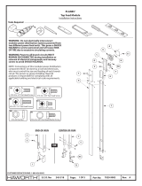
#10-32 x 3/8" Screw
(T) (F)
#8-32 x 1/4" Screw
9/64" Drill
7/32" Drill
A
B
F
C
D
S
T
E
P
F
#2
WARNING: Do not electrically interconnect
modular power distribution systems powered
from two dierent power feed units. This poses a
SHOCK HAZARD to service personnel and will
cause RISK OF FIRE due to excessive circulating
currents.
WARNING: All circuit power MUST REMAIN
DISCONNECTED during any installation or remov-
al of electrical components and raceway covers to
avoid SHOCK HAZARDS.
WARNING: Risk of re or electric shock. Complete
all drilling before installing electrical or communi-
cation wiring.
NOTE: Connections of this modular power distribu-
tion component MUST be done by a licensed electri-
cian, who must control the size and loading of each
branch circuit. The person or group installing
Haworth products is responsible for complying with
all applicable building and electrical code require-
ments. Compose Connections® top feed are designed
for a ceiling height of 10' from the oor.
Part No:
Page:
E.C.O. No:
CUSTOMER SERVICE PHONE: 1-800-426-8562
298-749 1 of 4 Rev: 1
7029-9991
Tools Required
End-of-Run Top Feed
Installation Instructions
COMPOSE CONNECTIONS®
D2
D3
D1
(D1)
1/4-20 x 3" Carriage Bolt
(D3)
Washer
(D2)
1/4-20 Nut

Part No:
Page:
E.C.O. No:
CUSTOMER SERVICE PHONE: 1-800-426-8562
298-749 2 of 4 Rev: 1
7029-9991
D
Check ceiling height (12' maximum)
Install service pole (D)Install mounting bracket (B)
10'
(3048mm)
B
C
(C)
#8-32 x 3/8" Screw
7/32"
D
D
D2
D3
D1
32
1
(D1)
1/4-20 x 3" Carriage Bolt
(D3)
Washer
(D2)
1/4-20 Nut
NOTE: If necessary
drill holes.
NOTE: If power pole (D)
needs to be shortened
remove excess from top.
D

Part No:
Page:
E.C.O. No:
CUSTOMER SERVICE PHONE: 1-800-426-8562
298-749 3 of 4 Rev: 1
7029-9991
Route power (R) Locate and cut hole in celing tile (G)
D
D
G
END-OF-RUN
4 5
R
Tie top feed (D) to building
6
D

P
T
A
S
#10-32 x 3/8" Screw
(T)
Install electrical box cover (S)
Install cover (P)
1 2
Separate ceiling bezel (H)
H
H
Install ceiling bezel (H)
F
9/64" Drill
F
A
(F)
#8-32 x 1/4" Screw
(F)
#8-32 x 1/4" Screw
Part No:
Page:
E.C.O. No:
CUSTOMER SERVICE PHONE: 1-800-426-8562
298-749 4 of 4 Rev: 1
7029-9991
7 8
9
10
NOTE: If cover (P) needs to
be shortened remove
excess from top.
/


