Page is loading ...

Tools Required
Part No: Rev:
Page:
E.C.O. No: 1 OF 5 7029-9903
CUSTOMER SERVICE PHONE: 1-800-426-8562
A245-518
H
G
A
B
CC1
D
E
F
J
E
C
CC
F
N
M1
#10-32 x 1/2" Pan Head Screw
(D)
Q
E
M1
#10-32 Hex Nut
(N)
PLANES®
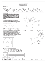
Top Feed Module
Installation Instructions
#2
WARNING: Do not electrically interconnect
modular power distribution systems powered from
two dierent power feed units. This poses a SHOCK
HAZARD to service personnel and will cause RISK
OF FIRE due to excessive circulating currents.
WARNING: Power to all branch circuits MUST
REMAIN DISCONNECTED during installation or
removal of electrical components and raceway
covers to avoid SHOCK HAZARDS.
NOTE: Connections of this modular power distribution
component MUST be done by a licensed electrician,
who must control the size and loading of each branch
circuit. The person or group installing Haworth
products is responsible for complying with all
applicable building and electrical code requirements.
#10-32 x 1/2" Flat Head Screw
(E)
#10-24 x 3/8" Pan Head Screw
(M1)
(C1)
#8-32 x 1/4" Screw
#10-24 x 3/8" Hex Head Washer Screw
(P)
OR
END-OF-RUN CENTER-OF-RUN

Part No: Rev:
Page:
E.C.O. No: 2 OF 5
CUSTOMER SERVICE PHONE: 1-800-426-8562
CENTER-OF-RUN OPTION
END-OF-RUN OPTION
1a
1b
Install brackets (Q)
Locate and install bracket (J)
7029-9903 A245-518
NOTE: Due to varying oor
construction fastener anchors
are not included and must be
eld supplied.
OR
J
M1
Q
#10-24 x 3/8" Pan Head Screw
(M1)

EC
Part No: Rev:
Page:
E.C.O. No:
CUSTOMER SERVICE PHONE: 1-800-426-8562
3 of 5 7029-9903 A245-518
23
Plumb cover (C) and locate and cut a hole in ceiling tile
4
5
#10-32 x 1/2" Flat Head Screw
(E)
OR
G
E
E
E
C
C
M1
C
#10-24 x 3/8" Pan Head Screw
(M1)
END-OF-RUN CENTER-OF-RUN

Install ceiling bezel (F)
M1
F
H
C
Part No: Rev:
Page:
E.C.O. No:
CUSTOMER SERVICE PHONE: 1-800-426-8562
4 of 5
Install outer cover (H)
Install electrical box cover (A)
A
C1
7029-9903 A245-518
#10-32 x 1/2" Screw
(D)
#10 Hex Nut
(N)
12
67
8
#10-24 x 3/8" Pan Head Screw
(M1)
(C1)
#8-32 x 1/4" Screw
B
N
D

10 Tie top feed (H) to building
H
9Cut & install grommet (K)
K
K
Part No: Rev:
Page:
E.C.O. No: 5 OF 5
CUSTOMER SERVICE PHONE: 1-800-426-8562
7029-9903 A245-518
/


