Page is loading ...

Rev:
Part No:
Page:
E.C.O. No:
CUSTOMER SERVICE PHONE: 1-800-426-8562
2245-593 1 of 5 7029-9996
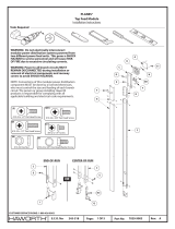
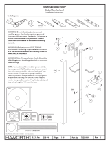
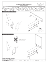
Tools Required
9/32”
Drill
C
D
B
H
A
E
G
F
12-11 x 2.5” A-Point Phillips Pan Hd Screw
(C)
4mm
3/4” OD x 5/16” ID x 1/10” Thick Washer
(F)
1/4-20 x .375 Bolt Connector Joint
(G)
1/2” x 2” x 1/16” Thick Foam Tape
(H)
Center Screen
Installation Instructions
ACTIVE COMPONENTS®
Scale 1 : 1
011/2
1/4 1/4

Rev:
Part No:
Page:
E.C.O. No:
CUSTOMER SERVICE PHONE: 1-800-426-8562
2245-593 2 of 5 7029-9996
10-7/16”
11-15/16”
14-15/16”
17-15/16”
10-7/16”
11-15/16”
14-15/16”
17-15/16”
1
Drill holes into Intuity rail for future use. Hole locations are described below.
42” Screen – Drill a 9/32" hole 10-7/16" in from each side of the rail
48” Screen – Drill a 9/32 " hole 11-15/16" in from each side of the rail
60” Screen – Drill a 9/32" hole 14-15/16" in from each side of the rail
72” Screen – Drill a 9/32" hole 17-15/16" in from each side of the rail
60” Screen
72” Screen
48” Screen
42” Screen
Hole Locations
D
D
D
D

Rev:
Part No:
Page:
E.C.O. No:
CUSTOMER SERVICE PHONE: 1-800-426-8562
2245-593 3 of 5 7029-9996
End View
2
60” Screen
72” Screen
48” Screen
42” Screen
Metal Insert Locations
A
D
A
A
Channel
for Metal
Insert
D
D
A AD
D
D
D
A A
A A
A
A
A A

Rev:
Part No:
Page:
E.C.O. No:
CUSTOMER SERVICE PHONE: 1-800-426-8562
2245-593 4 of 5 7029-9996
29 7/8”
CUSTOMER SERVICE PHONE: 1-800-426-8562
3The inserts/rods (B) on each end need to go as close to the edge as they can as the screen (E)
will ll the entire rail (D).
Tip: If the worksurfaces are installed,
lay the screen (E) on its side next to the
rail so that you can quickly line up
where the inserts/rods (B) should go.
3a The location of center rod for the 60” & 72” is as follows.
For 60” screen locate center rod 29 7/8" from the end of the rail.
For 72” screen locate center rod 35 7/8 " from the end of the rail.
D
B
60” Screen
DA A
E
G
F
D
72” Screen
DA A
35 7/8”
B

Note: Insert screw through
previously drilled holes.
C
Rev:
Part No:
Page:
E.C.O. No:
CUSTOMER SERVICE PHONE: 1-800-426-8562
2245-593 5 of 5 7029-9996
4
D
B
E
12-11 x 2.5” A-Point Phillips Pan Hd Screw
(C)
B
D
/
