Page is loading ...

sez.4d
−−−−
1
2 VOICE - Technical Manual
SECTION 4D
(REV. A)
CONCIERGE
SWITCHBOARD
Download from www.urmet.com Technical Manuals area.
SECTION CONTENTS
CONCIERGE SWITCHBOARD Ref. 1083/40 2
LIST OF DETAILS .............................................................................2
Keypad .........................................................................................2
Ringer ...........................................................................................2
Display ..........................................................................................2
DESCRIPTION OF CONNECTIONS .................................................2
TECHNICAL CHARACTERISTICS ....................................................2
INSTALLATION .................................................................................3
Table top installation ....................................................................3
Wall installation .............................................................................3
Video module installation .............................................................4
EXAMPLES OF SYSTEMS WITH DIFFERENT CAPACITIES ............5
OPERATING INSTRUCTIONS ..........................................................7
Usage types ..................................................................................7
Turning on and off the switchboard .............................................7
Day/night mode switching ............................................................7
Standby ........................................................................................7
Displaying name directory and calling a user ...............................7
Call from apartment stations ........................................................8
Stored calls coming from apartment stations ..............................8
Calling an apartment station using its code .................................8
Call from main station...................................................................9
Door lock release function ............................................................9
Management of codes for special services ..................................9
Open door indications ..................................................................9
Auto-on function ......................................................................... 10
Keypad lock activation/deactivation ..........................................10
Date/time adjustement ...............................................................10
Ringer volume .............................................................................10
Call diversion function to cordless phone ..................................10
Displaying codes and names in case of logical codes
operating mode ..........................................................................11
CONFIGURATION ..........................................................................11
Linguage .....................................................................................11
Busy time ....................................................................................11
Monitor presence .......................................................................11
System confi guration ..................................................................12
Call repeat (S+, S-) .....................................................................13
Communication interruption ......................................................13
Power-on password ...................................................................13
User codes type ......................................................................... 14
Function buttons ........................................................................14
Name management .................................................................... 14
Diagnostic services (polling) .......................................................15
Default values and restore ..........................................................16
PROGRAMMING VIA PC ................................................................16
CONFIGURATION AND OPERATION OF TWO 1083/40
SWITCHBOARDS IN MUTUALLY EXCLUSIVE MODE (X-OR).......16
References to operative instructions ..........................................16
System parameter confi guration ................................................17
Competence transfer from active to inactive switchboard ........17
Switchboard installation .............................................................18
Specifi c problems .......................................................................18
Permitted system types .............................................................. 18

2
−−−−
sec.4d
2 VOICE - Technical Manual
POSTAZIONI INTERNE VIDEOCITOFONICHE
CONCIERGE SWITCHBOARD Ref. 1083/40
12
ABC DEF
MNOJKLGHI
WXYZTUV
F1 F3F2
F4 F6F5
SHIFT
PQRS
3
456
78
0
9
The switchboard Ref. 1083/40 is only used in 2VOICE system to
perform:
communication function to/from apartment stations, with capability
to store not answered calls (up to 50);
concierge service (with or without local answer of calls coming from
main call stations and addressed to apartment stations).
The switchboard Ref. 1083/40 is available in only one version, table top
or wall mounting (see the chapter Installation); it can also be provided
with a video module Ref. 1732/41 with bracket Ref. 1732/955.
To connect the switchboard, use a dedicated system power supply
Ref. 1083/20A.
After confi guration, the switchboard is ready for all system users.
LIST OF DETAILS
12
ABC DEF
MNOJKLGHI
WXYZTUV
F1 F3F2
F4 F6F5
SHIFT
PQRS
3
456
78
0
9
12
ABC DEF
MNOJKLGHI
WXYZTUV
F1 F3F2
F4 F6F5
SHIFT
PQRS
3
456
78
0
9
1
2
3
9
5
1117
7
4
6
8
10
15
13
12
20
21
18
2219
16
14
–
–
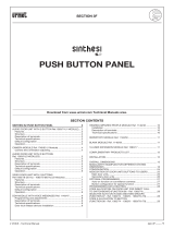
1 – On/off button with green led
2 – Day/Night mode switching button with green led
3 – Button used to display the list of the doors left open with red
led
4 – Button used to switch the communication to the apartment
station
5 – Button used to display the list of stored calls coming from
apartment stations with red led
6 – Button used to establish the communication between the door
unit and the apartment station
7 – Button used to call/confi rm
8 – Button used to display the log of the alarms received from
apartment stations with red led (for future uses)
9 – Button used to switch the communication to the call station
10 – Auto-on button
11 – Programmable functions buttons
12 – Alphanumeric keypad
13 – Button used to correct errors
14 – Secondary door lock release button
15 – Main door lock release button
16 – Second function button
17 – Clock setting button (date/time)
18 – Scroll arrows
19 – Display contrast adjustment
20 – Dedicated door phone
21 – Pedestrian door lock release button of the main call station
22 – Display
KEYPAD
The keypad includes dual function buttons used to enter call codes
used to call apartment stations, special codes, call station codes used
to open the door and search/enter user names. The functions of all the
buttons are described in detail in next paragraphs.
RINGER
The ringer is electronically modulated and the volume can be adjusted
on 5 levels, as described in the paragraph “Ringer Volume”.
DISPLAY
The switchboard is provided with a 10 or 20 characters on 5 rows
backlit display; the 5 rows give different information according to the
system status. The last row always indicates date and time (except
during confi guration).
The switchboard display is backlit with leds with a 10” timeout.
Backlight is enabled when the handset is picked up, when any button
is pressed and a call or an alarm indication is received.
DESCRIPTION OF CONNECTIONS
]
LINE Connection to 2Voice system
]
POWER Dedicated power supply Ref. 1083/20A connection
S+ Supplementary ringer connection positive
S- Supplementary ringer connection negative
TECHNICAL CHARACTERISTICS
Power supply (POWER): 48Vdc ±10%
Max. current consumption: 140mA
Max. switching voltage S+, S-: 30Vdc
Max. switching current: 100mAdc on resistive load
Operating temperature range: -5 ÷ 45°C
CONCIERGE SWITCHBOARD
TECHNICAL CHARACTERISTICS
CONCIERGE SWITCHBOARD Ref. 1083/40

sec.4d
−−−−
3
2 VOICE - Technical Manual
POSTAZIONI INTERNE VIDEOCITOFONICHE
INSTALLATION
TABLE TOP INSTALLATION
By default, the switchboard is confi gured for table top installation,
with the specifi c support which ensures the best inclination.
The wiring junction box must be wall mounted with the provided
double-sided adhesive tape or with screws and screws anchors.
WALL INSTALLATION
1 – Remove the table support and the two feet from the switchboard
bracket.
2 – Extract the switchboard fi xing hook.
3 – Remove the switchboard from the bracket.
4 – Remove the door phone cover of the switchboard.
5 – Unscrew the base of the switchboard door phone from the
bracket.
6 – Fix the bracket to the wall with screws and screw anchors.
1,5 ÷1,6 m
7 – Mount again the door phone base by screwing it to the bracket.
8 – Put again the door phone cover.
CONCIERGE SWITCHBOARD
INSTALLATION
CONCIERGE SWITCHBOARD Ref. 1083/40

4
−−−−
sec.4d
2 VOICE - Technical Manual
POSTAZIONI INTERNE VIDEOCITOFONICHE
9 – Put again the door phone body in its seat and fi x it with the locking
hook.
The wiring junction box must be wall mounted with the provided
double-sided adhesive tape or with screws and screws anchors.
VIDEO MODULE INSTALLATION
The video module, provided with the bracket Ref. 1732/91, can be
installed on the right of the switchboard.
1 – Fix the video module bracket to the switchboard bracket with two
little brackets and 4 screws which must be placed in the specifi c
seats.
2 – Extract the switchboard fi xing hook.
3 – Remove the switchboard from the bracket.
4 - Bracket (Ref. 1732/955) connection of the video module to the
switchboard bracket.
a) Cut the Video Adapter Cable (Ref. 1742/13A) as shown.
b) Insert the cut cable piece into the adapter connector.
Make the connections as the underlying drawing.
R1
A
B
B
(2)
(2)
(1)
A
R2
R1
1742/13A
Switchboard
Ref. 1732/41
V5
V3
R2
R1
R2
R1
R2
V3
V5
Video module
Ref.1732/41
+
Bracket
Ref.1732/955
R1 / A = Blue ; R2 = Yellow ; V3 = Blue ; V5 / B = Shielding
Note: (1) = Cable supplied with the Switchboard
(2) = Terminal block not supplied.
5 – Make a hole in the switchboard plastic side.
CONCIERGE SWITCHBOARD
INSTALLATION
CONCIERGE SWITCHBOARD Ref. 1083/40

sec.4d
−−−−
5
2 VOICE - Technical Manual
POSTAZIONI INTERNE VIDEOCITOFONICHE
CONCIERGE SWITCHBOARD
EXAMPLES OF SYSTEMS WITH DIFFERENT CAPACITIES
CONCIERGE SWITCHBOARD Ref. 1083/40
6 – Place again the switchboard body and fi x it with the locking
hook.
If the video module must be placed near a table top mounted
switchboard, before starting operations described above, install
the suitable support and the 2 feet provided with the video
module bracket.
EXAMPLES OF SYSTEMS WITH DIFFERENT
CAPACITIES
To connect the switchboard use the 2Voice dedicated cable,
observing the following distances:
Between switchboard and 2Voice dedicated power supply 5 m
Between switchboard and 4-user distributor Ref. 1083/55 50 m
Between switchboard and column interface Ref. 1083/50 50 m
Between switchboard and door units interface 50 m
Between switchboard and 2Voice power supply 50 m
Switchboard connection in door phone systems without call
stations
switchboard
switchboard
2Voice
power supply
for switchboard
2Voice
power supply
2Voice power supply
for switchboard
2VOICE
power supply
§
§
2Voice
power supply
for switchboard
switchboard
2VOICE
power supply
Switchboard connection in systems with one column and one call
station
switchboard
2VOICE
power supply
call
station
2Voice
power supply
for switchboard
Switchboard connection in systems with one column and up to
2 call stations
switchboard
column
interface
call
stations
call
stations
switchboard
2VOICE
power supply
column
interface
2VOICE
power supply
2Voice
power supply
for switchboard
2Voice
power supply
for switchboard

6
−−−−
sec.4d
2 VOICE - Technical Manual
POSTAZIONI INTERNE VIDEOCITOFONICHE
Switchboard connection in systems with one column and up to
4 call stations
switchboard
2VOICE
power supply
2VOICE
power supply
2VOICE
power supply
2VOICE
power supply
door units
interface
door units
interface
call stations
call stations
switchboard
2Voice
power supply
for switchboard
2Voice
power supply
for switchboard
Switchboard connection in systems with more than one column,
each one with some secondary call stations and 1 main call
station
switchboard
2VOICE
power supply
2VOICE
power supply
2VOICE
power supply
main
call station
column
interface
column
interface
2Voice
power supply
for switchboard
Switchboard connection in systems with 32 columns max., each
one with some secondary call stations and up to 4 main call
stations
main call stations
door units
interface
column
interface
column
interface
2VOICE
power supply
2VOICE
power supply
2VOICE
power supply
2VOICE
power supply
switchboard
2Voice
power supply
for switchboard
CONCIERGE SWITCHBOARD
EXAMPLES OF SYSTEMS WITH DIFFERENT CAPACITIES
CONCIERGE SWITCHBOARD Ref. 1083/40

sec.4d
−−−−
7
2 VOICE - Technical Manual
POSTAZIONI INTERNE VIDEOCITOFONICHE
OPERATING INSTRUCTIONS
USAGE TYPES
The switchboard operates according to its confi guration during the
installation phase and to its operating status. The possible switchboard
operation modes are described below.
SWITCHBOARD OFF
When the switchboard is off, it operates as it was not present in the
system. Calls coming from main call stations directly reach apartment
stations. Calls coming from apartment stations and addressed to the
switchboard are lost.
TC
SWITCHBOARD ON
When the switchboard is turned on, it resumes DAY or NIGHT
operation mode, previously confi gured.
NIGHT SERVICE
In this condition, the concierge service is disabled and calls
coming from main stations are directly sent to apartment stations.
The switchboard can receive calls from apartment stations; if not
answered, calls are saved in the memory. The switchboard can call
any apartment station.
TC
DAY SERVICE
In this condition, the switchboard performs the concierge service,
intercepting calls coming from main call stations and addressed to
apartment stations. The switchboard can receive calls from apartment
stations; if not answered, calls are saved in the memory (up to 50). The
switchboard can call any apartment station.
TC
TURNING ON AND OFF THE SWITCHBOARD
Case 1: switchboard without access password.
To turn the switchboard on, press the button
. The display shows:
VER. 3.0
1083/40
In this screen the software version number is indicated below.
After 2 seconds, the switchboard starts operating in the mode active
before it was turned off.
If the switchboard is in working mode DAY, the led (2) is on; if it is in
NIGHT mode, the led (2) is off.
To turn the switchboard off, keep the button SHIFT (16) pressed while
pressing the button
(1).
Case 2: switchboard with access password.
To turn the switchboard on, press the button (1). The display
shows:
VER. 3.0
1083/40
In this screen the software version number is indicated below.
After 2 seconds, the following screen is displayed:
PASSWORD
13/03/2010 15:30:30
Enter the access password programmed by the installer and press the
button (7). The switchboard starts operating in the mode active
before it was turned off.
If the switchboard is in working mode DAY, the led (2) is on; if it is in
NIGHT mode, the led (2) is off.
If the password entered is wrong or if one minute is elapsed from
power on, the switchboard turns off again.
DAY / NIGHT MODE SWITCHING
To switch from DAY to NIGHT mode, keep the button SHIFT (16)
pressed while pressing the button (2).
The operating mode DAY is indicated by the led (2) which turns on, in
NIGHT mode the led stays off.
STANDBY
13/03/2010 15:30:30
During standby, the display only shows date and time.
DISPLAYING NAME DIRECTORY AND CALLING A
USER
When pressing the buttons or (18), the display shows the
following screen
CONCIERGE SWITCHBOARD
OPERATING INSTRUCTIONS
CONCIERGE SWITCHBOARD Ref. 1083/40

8
−−−−
sec.4d
2 VOICE - Technical Manual
POSTAZIONI INTERNE VIDEOCITOFONICHE
13/03/2010 15:30:30
yyyyyyyyyyyyyyyyyyyy
yyyyyyyyyyyyyyyyyyyy
NAME LIST: xxxx/nnnn
where:
xxxx progressive index of selected name
nnnn total number of names in the directory
yyyyyy user name
To search for a name, scroll the list with the buttons or
(18) or press an alphanumeric button (12) to reach the fi rst user which
name starts with the selected letter (for example, to search for the
name ROSSI, press an arrow button to gain access to the directory
and the button 7 for 3 times to select letter R; then search for the user
with arrows).
To call the selected user pick the handset up and press the button
(7).
CALL FROM APARTMENT STATION
During a call coming from an apartment station, the switchboard rings
and the display shows the following screen:
13/03/2010 15:30:30
yyyyyyyyyyyyyyyyyyyy
yyyyyyyyyyyyyyyyyyyy
CALL FROM: iiiii
where:
iiiii: physical code of the caller (Liiii – in case of logical code)
yyyyyy: caller name
The switchboard attendant can answer the call by picking the handset
up; if he does not answer within 10 seconds, the call is stored in the
call memory (50 max.).
STORED CALLS COMING FROM APARTMENT
STATIONS
If there is at least one stored call, the led of call memory (5) is on.
When pressing the button (5), the following screen is
displayed:
13/03/2010 15:30:30
yyyyyyyyyyyyyyyyyyyy
yyyyyyyyyyyyyyyyyyyy
MEM.: nn iiiii
where:
nn: call progressive number in memory
iiiii: physical code of the caller (Liiii – in case of logical code)
yyyyyy: caller name
With the buttons
or (18) the user can scroll the list of stored
calls (the total number of stored calls is 50).
When the memory is full, no more calls are stored in the
memory.
After selecting a call stored in the memory, the user can be called by
picking the handset up and pressing the button
(7).
In this case, the indication is automatically deleted from the memory.
§
To manually delete a call indication, select it with the buttons
or (18), press the button X (13) and press the button
1
to
confi rm.
CALLING AN APARTMENT STATION USING ITS
CODE
By entering a physical or logical code with the keypad, the display
shows the following screen:
13/03/2010 15:30:30
iiiii
where:
iiiii is the entered code.
Initial 0 of a code can be omitted.
The user can be called by pressing the button (7) with the handset
picked up.
After the call has been sent to an apartment station, the display
shows:
-iiiii
13/03/2010 15:30:30
yyyyyyyyyyyyyyyyyy
yyyyyyyyyyyyyyyyyy
CALL FOR: iiiii
where:
iiiii: physical code of the called user (Liiii – in case of logical
code)
yyyyyy: name of the called user
When the switchboard establishes a communication with the called
user, the display shows the following screen:
iiiii
13/03/2010 15:30:30
yyyyyyyyyyyyyyyyyy
yyyyyyyyyyyyyyyyyy
USER IN COMM.: iiiii
where:
iiiii: physical code of the called user (Liiii – in case of logical
code)
yyyyyy: name of the called user
BUSY SIGNAL
When the switchboard performs a call or an auto-on function, but the
system is busy, the following screen appears for 2 seconds:
BUSY
13/03/2010 15:30:30
§
CONCIERGE SWITCHBOARD
OPERATING INSTRUCTIONS
CONCIERGE SWITCHBOARD Ref. 1083/40

sec.4d
−−−−
9
2 VOICE - Technical Manual
POSTAZIONI INTERNE VIDEOCITOFONICHE
CALL FROM MAIN STATION
During the concierge service in DAY mode (interception of calls
coming from main stations and call forwarding to apartment stations,
if required), when the switchboard receives a call from a main call
station, the following screen is displayed:
eefiiiiic
13/03/2010 15:30:30
yyyyyyyyyyyyyyyyyyyy
yyyyyyyyyyyyyyyyyyyy
CALL FOR: iiiii
where:
ee: number of the main call station (00÷03)
f: is a symbol showing the status of communication; it can
be:
... When the switchboard has not yet answered the call
When the switchboard is in communication with the
call station
When the switchboard is in communication with an
apartment station
When the switchboard has established a
communication between the main call station
and an apartment station.
iiiii: physical code of the called user (Liiii – in case of logical
code)
yyyyyy: name of the called user
c: when the symbol BELL appears in this position, it means
that the switchboard has not yet called the apartment
station iiiii; if the attendant presses the button (7), the
user iiiii is directly called and this symbol disappears.
After receiving a call, the switchboard can call users by entering the
code iiiii followed by the button (7). When in this condition, the
switchboard attendant will be able to:
establish again a communication with the call station (9)
call again the user (4)
establish a communication between the call station and the user
(6)
When in this last condition, the switchboard can not establish
again a communication with the call station or with the user.
If the switchboard attendant has not yet answered the call coming
from the call station, by pressing the auto-on button (10)
the attendant can see images coming from the additional cameras
connected to the main station.
DOOR LOCK RELEASE FUNCTIONS
At any time, the switchboard allows to open any door associated to
the main or secondary call station.
Main entrance door opening
The following 2 conditions are possible:
1) After a call coming from a main call station:
when the switchboard is performing the concierge service in DAY
mode and is in communication with a main call station, the attendant
can:
press the button
(15) or the door lock release button on the
handset to open the pedestrian door of the caller main station;
press the button SHIFT (16) + (15) to open the driveway gate
of the caller main station.
2) In any other situation:
when the switchboard is NOT in conversation, to open the pedestrian
door of a main call station press the button
(15), enter the ID
code of the main call station (0÷3) and press the button
(7) to
open the door.
–
–
–
§
•
•
13/03/2010 15:30:30
PRESS TO OPEN
MAIN DOOR.: 2
when the switchboard is NOT in conversation, to open the driveway
gate of a main call station press the button SHIFT (16) + (15),
enter the ID code of the main call station (0÷3) and press the button
(7) to open the gate. The display is similar to the previous one.
When the switchboard is NOT in conversation, to open the
pedestrian door of a secondary call station press the button
(14) followed by the button (7), enter the ID code of the
secondary call station (0÷3), enter the address of the secondary
(0÷1) and press the button (7) to open the door.
13/03/2010 15:30:30
PRESS TO OPEN
SEC. DOOR: 15 - 0
In this example, the attendant has opened the door connected to
the secondary call station with ID = 15 and secondary address 0.
When the switchboard is not in conversation, to open the driveway
gate of a secondary call station press the button SHIFT (16) +
(14) followed by the button (7), enter the ID code of the
secondary call station (0÷31), enter the address of the secondary
(0÷1) and press the button (7) to open the gate. The display is
similar to the previous one.
MANAGEMENT OF CODES FOR SPECIAL
SERVICES
The switchboard is enabled to manage electric actuators by using
decoders for special services Ref. 1083/80.
Press and keep the button “0” pressed for 3s and enter the actuator
special code (1 ÷ 255); the display shows the following screen:
13/03/2010 15:30:30
PRESS TO SEND
SPECIAL CODE: 1
Confi rm the command with the button (7).
After the button
(7) has been pressed, the display returns to
standby mode.
It also possible to use the function buttons (11), which can be
programmed to directly activate special decoders (see in the chapter
“Confi guration” the paragraph “Function Buttons”).
OPEN DOOR INDICATIONS
The switchboard is provided with a led (3), used to indicate the status
of doors of main and secondary call stations.
The feature depends on the status of the terminal pin SP in the call
stations and needs an open door sensor.
The following operating states are possible:
led off: all main and secondary entrance doors are closed;
•
•
•
CONCIERGE SWITCHBOARD
OPERATING INSTRUCTIONS
CONCIERGE SWITCHBOARD Ref. 1083/40

10
−−−−
sec.4d
2 VOICE - Technical Manual
POSTAZIONI INTERNE VIDEOCITOFONICHE
led on: on one or more main or secondary entrance doors, the
door is open. The condition of open door is signalled
by call stations only if this event lasts for at least 30
seconds.
When the led (3) is on, by pressing the button (3) the attendant can
access the list of doors left open:
13/03/2010 15:30:30
OPENED DOOR
SECONDARY: 13-1
In the example, the indication shows that the door of the secondary
call station with ID = 13 and secondary address 1 is open.
Use the buttons or (18) to scroll the list of open doors.
AUTO-ON FUNCTION
The switchboard provided with an optional video module can perform
the auto-on function on main call stations. This means that the
switchboard attendant can establish a video connection (and also
audio, if required) with a main call station even if no one has called
him from that station.
To perform the auto-on function, press the button (10); the
additional video module of the switchboard shows the image coming
from the main call station with ID=0; to display images coming from
the other additional cameras of the main station 0 and then images
coming from other main call stations, press again the button
(10). The display shows:
00 - SWTCHB
13/03/2010 15:30:30
AUTO ON
If the attendant wants to establish an audio communication with the
main call station which is sending images, he can pick the handset up,
as if the switchboard had been called.
KEYPAD LOCK ACTIVATION / DEACTIVATION
If the attendant must leave his station, he can activate the keypad
lock. To do this, press at the same time the buttons SHIFT (16) and
X (13)
13/03/2010 15:30:30
KEYBOARD LOCKED
If the keypad is locked, the switchboard does not execute commands
from the keypad, included DAY/NIGHT service switching and turning
off. To deactivate the keypad lock, repeat the above described
operation.
The keypad lock condition is kept even if the switchboard is unpowered
and then powered.
DATE/TIME ADJUSTMENT
Date and time can be confi gured/changed by pressing at the same
time the buttons SHIFT (16) +
(17). The display shows:
__/__/____ __:__:__
DATE/TIME ADJUSTMENT
Date and time must be entered using the numeric keypad (12) as
follows: Day/Month/Year/Hour/Minutes/Seconds.
After entering the last digit of seconds, confi rm with the button
(7).
If date/time settings must not be changed, press the button X (13) for
3 seconds.
RINGER VOLUME
When the device is in standby mode, the ringer volume can be
adjusted; for adjustment, keep the button SHIFT (16) pressed and
select the desired volume (1÷5) with the buttons and (18).
During volume adjustment, the display shows the following screen:
13/03/2010 15:30:30
PRESS ↓↑ TO SET
RING VOLUME: 1
CALL DIVERSION FUNCTION TO CORDLESS
PHONE
It is possible to temporarily divert the switchboard call reception
service (according to the operating status day/night) to a cordless
phone connected to an interface Ref. 1083/67, suitably connected
to the system and confi gured. To do this, press the function button
SHIFT (16) + F1 or SHIFT (16) + F2 or SHIFT (16) + F3.
The function buttons F1, F2 and F3 must be previously
programmed for the function.
The display shows:
13/03/2010 15:30:30
DIVERTED TO: ddddd
where:
ddddd is the physical code of the interface Ref. 1083/67 which
manages the call diversion. In this condition, the telephone connected
to 1083/67 can only answer the calls coming from apartment stations.
If during diversion the switchboard operating status is “day”, from
this telephone the attendant can also answer calls coming from main
call stations and open the door. In any case, calls can not be diverted
to apartment stations.
With the function “call diversion to cordless phone” active, from
the switchboard the attendant can only deactivate the function by
pressing again the same button SHIFT (16) + button function which
has activated the call diversion.
§
CONCIERGE SWITCHBOARD
OPERATING INSTRUCTIONS
CONCIERGE SWITCHBOARD Ref. 1083/40

sec.4d
−−−−
11
2 VOICE - Technical Manual
POSTAZIONI INTERNE VIDEOCITOFONICHE
DISPLAYING CODES AND NAMES IN CASE OF
LOGICAL CODES OPERATING MODE
If the switchboard is confi gured with logical codes, in all screens with
user codes, these are displayed with their logical code preceded by
“L”. If the code can not be displayed, the respective physical code is
displayed (i.e. without the prefi x “L”).
For example, if a call is received from the main station 1 which has
called the user of the column 14 with dip switch set to value 123:
if the received physical code 14123 in the switchboard directory is
associated to the user ROSSI with logical code 1000, the display
shows:
01 - L1000
13/03/2010 15:30:30
ROSSI
CALL FOR: L1000
if the received physical code 14123 in the switchboard directory is
NOT associated to any user, the display shows:
01 - 14123
13/03/2010 15:30:30
CALL FOR: 14123
–
–
CONCIERGE SWITCHBOARD
COFIGURATION
CONCIERGE SWITCHBOARD Ref. 1083/40
CONFIGURATION
To access the confi guration menu, keep the button SHIFT (16) pressed
and press repeatedly and quickly the button (4). The fi rst screen
displayed is the screen for selecting the language.
To quit confi guration, keep the button X (13) for 3 seconds in any
screen.
However, the switchboard quits the confi guration mode for time-
out after 300 seconds of inactivity.
LANGUAGE
In this screen the language of switchboard interface can be selected.
LANGUAGE
ENGLISH
Press the buttons and (18) to select the desired language
and press the button (7) to confi rm and go to the next screen.
BUSY TIME
The value set in this screen defi nes the assured communication time,
starting from the moment of the answer to a call.
BUSY TIME
(1,10,20,30,...,70S)
10
To change the busy time, use the buttons and (18). 8
different timings can be set: 1s, 10s, 20s, 30s, 40s, 50s, 60s, 70s. This
value must be the same as that confi gured in system call stations.
When the busy time has been selected, press the button (7) to
confi rm and go to the next screen.
MONITOR PRESENCE
In this screen, it can be specifi ed if the optional additional monitor
is present or not. Allowable values are 0=NO (no additional video
module) and 1=YES (presence of additional video module).
MONITOR
(0=NO , 1=YES)
1
To set this parameter, use the buttons and (18) and press
the button (7) to confi rm and go to the next screen.

12
−−−−
sec.4d
2 VOICE - Technical Manual
POSTAZIONI INTERNE VIDEOCITOFONICHE
SYSTEM CONFIGURATION
IN RISER
(0=NO , 1=YES)
0
Set YES with the buttons and (18) only if the switchboard
is installed in a one-riser system in the following cases:
1) system with 0, 1, 2, 3 or 4 main stations (with interface Ref.
1083/75, if present) without secondary stations and without
column interfaces Ref. 1083/50;
2) system with a single column interface Ref. 1083/50 without
connection LINE IN and with 0, 1, 2 call stations.
Press the button
(7) to confi rm and go to the next screen.
CONCIERGE SWITCHBOARD
CONFIGURATION
CONCIERGE SWITCHBOARD Ref. 1083/40
System configuration
in riser = YES
switchboard
power supply
power supply
power supply
main call stations
door units
interface
switchboard
call station
power supply
power supply
System configuration
in riser = YES
switchboard
power supply
call stations
power supply
column
interface
System configuration
in riser = YES
System configuration
in riser = NO
switchboard
power supply
power supply
power supply
power supply
main call station
secondary
call stations
secondary
call stations
column
interface
column
interface

sec.4d
−−−−
13
2 VOICE - Technical Manual
POSTAZIONI INTERNE VIDEOCITOFONICHE
CALL REPEAT (S+, S-)
In this screen the user can defi ne if the ringer repeat must be activated
or not and if this must be activated only for special call types; the
following screen appears:
S+ S-
(0=NO,1=EX,2=IN,3=A)
1
The values selectable with the buttons and (18) are:
0 call repeat on S+ and S- disabled
1 call repeat on S+ and S- enabled only for calls coming from main
call stations
2 call repeat on S+ and S- enabled only for calls coming from
apartment stations
3 call repeat on S+ and S- enabled for all the calls
Press the button (7) to confi rm and go to the next screen.
COMMUNICATION INTERRUPTION
In this screen the user can defi ne if the interruption of a call during off-
hook waiting time or assured communication time must be enabled
or not.
During a call, a conversation, or an auto-on function with or without
audio, the involved column or, more in general, the system devices
in busy state, can be interrupted or not by a call coming from a call
station, according to the confi guration of this switch.
INT. COMM.
(0=NO , 1=YES)
0
CONCIERGE SWITCHBOARD
COFIGURATION
CONCIERGE SWITCHBOARD Ref. 1083/40
System configuration
in riser = NO
switchboard
power supply
power supply
power supply
power supply power supply
main call stations
secondary
call
stations
secondary
call stations
column
interface
column
interface
door units
interface
To set this parameter, use the buttons and (18) and press
the button
(7) to confi rm and go to the next screen.
This value must be the same as that confi gured in system call
stations.
POWER-ON PASSWORD
In this screen the user can set the password required when the
switchboard is turned on.
PASSWORD
000000
Press the button X (13) to delete the current password and enter
the new one, using the numeric keypad (12). The password can be
composed by 6 numeric characters max.
If the user does not want to protect the switchboard power-on with a
password, set it to 000000.
When the parameter has been confi gured, press the button (7) to
confi rm and go to the next screen.
USER CODES TYPE
In this screen it is possible to confi gure the user code type, physical
or logical.
Physical code: users are called with a 5-digit code as follows:
ccnnn, where cc indicates the riser column (from 00 to 31) and nnn
indicates the number of the apartment (from 000 to 127)
Logical code: users are called with a a number of 1 to 4 digits
from 1 to 9999. To use the logical codes, the names must be
programmed, assigning the logical call code to the physical code
of the apartment.
–
–

14
−−−−
sec.4d
2 VOICE - Technical Manual
POSTAZIONI INTERNE VIDEOCITOFONICHE
CODE TYPE
(0=PHYSIC, 1=LOGIC)
0
To set this parameter, use the buttons and (18) and press
the button (7) to confi rm and go to the next screen.
In order to use logical code type, each code must be associated
to a physical code in the directory.
FUNCTION BUTTON
In the switchboard there are 6 programmable function buttons (11).
The following codes can be associated to each function button:
a special code to activate the special decoder Ref. 1083/80
a code used to divert a call to a telephone managed by the interface
Ref. 1083/67
For each of the 6 function buttons the setting screen is the following:
F1 BUTTON
(0=NO,1=SPEC,2=TEL)
0
To confi gure this parameter use the buttons and (18):
if the value 0 is selected, no special function will be assigned to
the button,
if the value 1 is selected, the function of special code sending will
be associated to the button and the display shows the following
screen:
F1 BUTTON
(0=NO,1=SPEC,2=TEL)
TYPE SPECIAL CODE
1
Enter the special code to be associated to the button (1÷255) and
press the button (7) to confi gure the next function button;
if the value 2 is selected, the call diversion function will be associated
to the button and the display shows the following screen:
F4 BUTTON
(0=NO,1=SPEC,2=TEL)
TYPE DIVERTING CODE
2
Enter the physical code which is the diversion destination and press
the button (7) to confi gure the next function button. This function
is available only for buttons F4, F5, F6.
The same procedure can be used to program the remaining 5 function
buttons.
§
•
•
•
•
•
CONCIERGE SWITCHBOARD
CONFIGURATION
CONCIERGE SWITCHBOARD Ref. 1083/40
NAME MANAGEMENT
NAMES
(0=CLEAR ALL)
(1=INS,2=MOD,3=DEL)
In this screen the user can enter, change or delete a user from the
device.
To enter a name, select
1
on the numeric keypad (12).
NAME INS.
PAOLO
ROSSI
PHY:00012 LOG:1000
With the alphanumeric keypad enter the physical code followed by
the button (7), the logical code (this one is not requested if the
device is programmed to operate with physical codes) followed by the
button (7) and then enter the user name using the numeric keypad
as it was the keypad of a mobile.
Button 1 touch 2 touches 3 touches 4 touches 5 touches
1 Blank 1
2A B C 2
3D E F 3
4G H I 4
5J K L 5
6M N O 6
7P Q R S 7
8T U V 8
9WXYZ9
Symbols can be selected with the buttons and (18).
When all data have been entered, press the button
(7) to
confi rm.
When names are being entered, the following confi gurations are not
accepted by the system:
2 users with the same name
In logical code mode, enter 2 users with different physical code and
the same logical code.
To change a name, select
2
on the numeric keypad (12):
NAME MOD.
PAOLO
ROSSI
PHY:00012 LOG:1000
0001/0083
The progressive number of the current name and the total number of
names stored in the memory appear in the second row.
Scroll the list using the buttons and (18) and press the
button (7) to select the name to be changed. Follow the same
procedure described in the section concerning name entering.
When all data have been entered, press the button (7) to confi rm
and store data or press X (13) to delete.
•
–
–
•

sec.4d
−−−−
15
2 VOICE - Technical Manual
POSTAZIONI INTERNE VIDEOCITOFONICHE
To delete a name, select
3
on the numeric keypad (12):
DEL. NAME
PAOLO
ROSSI
PHY:00012 LOG:1000
0001/0083
Scroll the list using the buttons and (18) and select the
name to be deleted, then press the button (7). After a confi rm
request, the name will be deleted.
To delete all the list stored in the memory, select
0
on the numeric
keypad (12) and the display will show the following screen for name
deleting:
LIST DEL.
(0=NO , 1=YES)
DELETE ALL NAMES?
Press
1
on the numeric keypad (12) to delete all the names or
0
to
cancel the operation and return to the initial screen.
The confi guration is kept even if the list is deleted
DIAGNOSTIC SERVICES (POLLING)
This screen allows to poll apartment stations (AS), main call stations
(MCS) and secondary call stations (SCM) present in the system:
POLLING
1=AS, 2=MCM, 3=SCM)
(0=NO POLLING
0
If the value 0 is entered, no query is performed and the switchboard
returns to the beginning of the confi guration menu.
By selecting with the buttons and (18) the value 1, the
following screen is displayed:
AS POLL.
INTERNAL CODE: .
PHYSICAL CODE:.....
Enter the apartment station physical code, press the button (7),
enter the internal code and press the button
(7) to poll the device;
after few seconds, the display will show the device status and FW
version:
•
•
§
AS POLL.
PRESENT FW: 3.0
INTERNAL CODE.: 1
PHYSICAL CODE: 21000
or, if the device has not answered:
AS POLL.
ABSENT !!
INTERNAL CODE.: 1
PHYSICAL CODE: 21000
By selecting with the buttons and (18) the value 2, the
display shows the following screen:
MCM POLL.
ID CODE: 2
Enter the ID code of the secondary call station, press the button
(7) to poll the device; after few seconds, the display will show the
device status and FW version:
MCM POLL.
PRESENT FW: 3.0
ID CODE: 2
or, if the device has not answered:
MCM POLL.
ABSENT !!
ID CODE: 2
By selecting with the buttons and (18) the value 3, the
display shows the following screen:
SCM POLL.
ADDRESS: 0
ID CODE: 03
Enter the ID code of the secondary call station, press the button
(7), enter the address and press the button (7) to poll the device;
after few seconds, the display will show the device status and FW
•
•
CONCIERGE SWITCHBOARD
CONFIGURATION
CONCIERGE SWITCHBOARD Ref. 1083/40

16
−−−−
sec.4d
2 VOICE - Technical Manual
POSTAZIONI INTERNE VIDEOCITOFONICHE
version:
SCM POLL.
PRESENT FW: 3.0
ADDRESS: 0
ID CODE: 03
or, if the device has not answered:
SCM POLL.
ABSENT !!
ADDRESS: 0
ID CODE: 03
DEFAULT VALUES AND RESTORE
The switchboard factory defaults are:
Language: Italian
Busy time: 30 sec.
Monitor presence: no
System confi guration: no
Call repeat: disabled
Communication interruption: no
Power-on password: no (000000)
User code type: physical
Function buttons: not programmed
To restore these values, unpower the switchboard, keep the buttons X,
8, 6 pressed and power the switchboard on waiting for few seconds.
This operation does not delete the name directory.
PROGRAMMING VIA PC
The switchboard is provided with a USB port for easy programming of
confi guration data and name directory.
Access the confi guration menu by keeping the button SHIFT (16)
pressed and pressing repeatedly and quickly the button (4).
Connect the switchboard to the PC where the software 2Voice_PC
has been installed (it can be downloaded from www.urmet.com) and
perform the programming procedure described in the instruction
manual of 2Voice_PC software.
CONFIGURATION AND OPERATION OF TWO
1083/40 SWITCHBOARDS IN MUTUALLY
EXCLUSIVE MODE (X-OR)
Below are all instructions how to install two switchboards in mutually
exclusive mode, i.e. one active switchboard at a time in the same
system.
In detail, the active switchboard can transfer system competences to
the inactive switchboard, which remains listening in stand-by.
Competencies are the functions performed by the switchboard in day
or night mode.
This service is available:
with FW versions higher than or equal to 4.0
in the system types described below only
Warning : The two conditions must coexist.
REFERENCES TO OPERATIVE INSTRUCTIONS
Some operative instructions are provided below.
In detail:
list of details
how to access the menu
how to exit the menu
menu structure
how to restore default settings
how to deactivate call diversion to cordless
LIST OF DETAILS
12
ABC DEF
MNOJKLGHI
WXYZTUV
F1 F3F2
F4 F6F5
SHIFT
PQRS
3
456
78
0
9
12
ABC DEF
MNOJKLGHI
WXYZTUV
F1 F3F2
F4 F6F5
SHIFT
PQRS
3
456
78
0
9
1
2
3
9
5
1117
7
4
6
8
10
15
13
12
20
21
18
2219
16
14
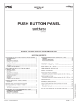
1 – On/off button with green led
2 – Day/Night mode switching button with green led
3 – Button used to display the list of the doors left open with red
led
4 – Button used to switch the communication to the apartment
station
5 – Button used to display the list of stored calls coming from
apartment stations with red led
6 – Button used to establish the communication between the door
unit and the apartment station
7 – Button used to call/confi rm
8 – Button used to display the log of the alarms received from
apartment stations with red led (for future uses)
9 – Button used to switch the communication to the call station
10 – Auto-on button
11 – Programmable functions buttons
12 – Alphanumeric keypad
13 – Button used to correct errors
14 – Secondary door lock release button
15 – Main door lock release button
16 – Second function button
17 – Clock setting button (date/time)
18 – Scroll arrows
19 – Display contrast adjustment
20 – Dedicated door phone
21 – Pedestrian door lock release button of the main call station
22 – Display
•
•
•
•
•
•
•
•
CONCIERGE SWITCHBOARD
PROGRAMMING VIA PC
CONCIERGE SWITCHBOARD Ref. 1083/40

sec.4d
−−−−
17
2 VOICE - Technical Manual
POSTAZIONI INTERNE VIDEOCITOFONICHE
HOW TO ACCESS THE MENU
Holding the SHIFT button (16) pressed, and repeatedly and rapidly
press the button (4) to open the confi guration menu. The language
selection page is the fi rst one to appear.
HOW TO EXIT THE MENU
Hold the X button (13) pressed on any page for three seconds to exit
confi guration mode. In all cases, the switchboard will exit confi guration
mode by timeout after 300 seconds of inactivity.
MENU STRUCTURE
The menu structure is show for the sake of simplicity below.
LANGUAGE
ENGLISH
BUSY TIME
(1,10,20,30,...,70S)
10
MONITOR
(0=NO , 1=YES)
1
IN RISER
(0=NO , 1=YES)
0
S+ S-
(0=NO,1=EX,2=IN,3=A)
1
INT. COMM.
(0=NO , 1=YES)
0
PASSWORD
000000
CODE TYPE
(0=PHYSIC, 1=LOGIC)
0
F1 BUTTON
(0=NO,1=SPEC,2=TEL)
0
NAMES
(0=CLEAR ALL)
(1=INS,2=MOD,3=DEL)
POLLING
1=AS, 2=MCM, 3=SCM)
(0=NO POLLING
0
SWI ID #
ID CODE: 00
HOW TO RESTORE DEFAULT SETTINGS
To restore default settings, switch off the switchboard, hold the X, 8,
6 buttons pressed and switch the switchboard back on. Wait for a few
seconds. This operation will not clear the name repository.
HOW TO DEACTIVATE CALL DIVERSION TO CORDLESS
To deactivate this function, press the SHIFT button (16) and the
function button used to activate the call diversion function.
(The F4, F5, F6 function buttons must have been previously
programmed for the function).
SYSTEM PARAMETER CONFIGURATION
A univocal ID must be assigned to each switchboard to be able to use
them in the same system.
For correct operation, make sure that the IN RISER parameter is set
to 0 for each switchboard.
Competences will not be transferred if either switchboard is not set
correctly.
IN RISER
(0=NO , 1=YES)
0
The SWI ID # parameter, which can be selected using the and
buttons (18), is used to defi ne the confi guration menu.
The identifi cation (ID CODE) of one switchboard must be equal to 00,
while the other switchboard must be set to 01.
SWI ID #
ID CODE: 01
SWI ID #
ID CODE: 00
To set ID CODE to 01, press 1 on the alphanumeric keypad (12)
and press
(7) to confi rm.
To set ID CODE to 00, press X (13) and press (7) to confi rm.
Warning:
The ID coherent setting of the switchboards is essential for
correct operation of the two devices in the system.
The SWI ID # parameter must be set to 00 in systems in which only
one switchboard is used. This is the default parameter setting, i.e. the
one which will be set after restoring the device.
COMPETENCE TRANSFER FROM ACTIVE TO
INACTIVE SWITCHBOARD
This service is useful in installations in which two switchboard
operators need to work alternatively from different locations.
In these instructions:
the active switchboard is the one with competencies in the
system
the inactive switchboard is the other device which is not
performing any function (but which is listening and is ready to
accept transfer of competences)
The active switchboard may be:
off (green LED of the [ON/OFF 1] button off)
on in day or night mode (green LED of the [ON/OFF 1] button on)
The inactive switchboard has only one operating mode and can only
receive competences (if required to do so by the active switchboard).
The inactive switchboard may be:
off (green LED of the [ON/OFF 1] button blinks slowly)
Warning:
Only the switchboard which is active and on can transfer
competencies to the inactive switchboard.
Transfer of competences can be requested by the active switchboard
when it is in stand-by mode, i.e. is not performing an activity (e.g.
incoming or outbound calls, auto-on etc.).
Competences can be transferred from the switchboard which is
active and on by holding the SHIFT (16) and (6) buttons pressed
until three dots moving from left to right appear on the switchboard
display.
This step will last for a few seconds (according to the traffi c present in
the system) and a fi rst confi rmation beep will be generated when the
button (6) is pressed.
...
12/09/2014 09:41:55
If the transfer is completed successfully, the display will go off, the
green LED on the [ON/OFF 1] button will blink slowly and a second
confi rmation beep will be generated. The inactive switchboard which
•
•
•
•
•
•
•
CONCIERGE SWITCHBOARD
CONFIGURATION AND OPERATION OF TWO 1083/40 SWITCHBOARDS IN MUTUALLY
EXCLUSIVE MODE (X-OR)
CONCIERGE SWITCHBOARD Ref. 1083/40

18
−−−−
sec.4d
2 VOICE - Technical Manual
POSTAZIONI INTERNE VIDEOCITOFONICHE
receives the competencies will generate a beep.
If the transfer fails (e.g. because the inactive switchboard cannot
be reached), the state of the active switchboard which started the
transfer sequence will not change and four beeps will be heard
(deterrent tone).
Transferring competences also means transferring the current
operating mode of active switchboard, i.e.:
the active switchboard in day mode transfers competencies: the
switchboard which receives the competencies will be activated
in day mode
the active switchboard in night mode transfers competencies: the
switchboard which receives the competencies will be activated
in night mode
The active switchboard cannot transfer competencies when it is off.
Warning:
The competences transfer procedure can be carried out if calls or
alarms are stored on the active switchboard but the stored data
will not be transferred with the competencies. The data will remain
stored on the switchboard which transfers the competences in all
cases.
SWITCHBOARD INSTALLATION
The following procedure may be used in systems in which a switchboard
is already present and in systems in which two switchboards must be
installed from scratch.
Warning:
In systems in which a switchboard is already present, make sure
that the FW of the installed switchboard is appropriate (≥ 4.0)
for the required type of performance and that the system type is
suitable for using two switchboards.
FIRST SWITCHBOARD
Make sure that the fi rst switchboard is plugged into its telephone
socket.
Make sure that the IN RISER parameter of the fi rst switchboard
is set to 0.
Check that the SWI ID # parameter on the fi rst switchboard is set
to 00 and exit confi guration.
SECOND SWITCHBOARD
Restore default settings using the restore default settings
procedure.
This step is not required on new switchboards but is necessary if
the switchboard has been used before.
Make sure that the fi rst switchboard is plugged into its telephone
socket.
Make sure that the IN RISER parameter on the second switchboard
is set to 0.
Set the SWI ID # parameter on the second switchboard to 01
and press (7) to confi rm. This operation will cause the second
switchboard to restart. The second switchboard will be inactive
and the fi rst switchboard will be active.
SPECIFIC PROBLEMS
CALL DIVERT SERVICE TO A REF. 1083/67 INTERFACE
If the active switchboard is diverting calls to a ref. 1083/67 interface,
it will not be possible to transfer the competences as long as the call
divert service to cordless remains active.
HOW TO REMOVE AN INACTIVE SWITCHBOARD FROM A
SYSTEM
In this case, the switchboard will not work until the default settings are
restored during the restore default settings procedure.
Warning:
A switchboard in inactive state can only change stated after
having received competences from an active switchboard.
•
•
•
•
•
•
•
•
•
•
NO POWER IN ONE OR MORE PARTS OF THE SYSTEM
The state of the two switchboards (one active, one inactive) present
in the system is stored in a non-volatile memory and consequently
once the states are consolidated switching normal power on and off
is not a problem.
However, the power could be cut off during the competences transfer
procedure and this will compromise success of the operation.
In these cases, the following confi guration will be assumed if the two
switchboards detect inconsistencies when normal power is restored:
The switchboard with SWI ID # = 00 will be the active
switchboard
The switchboard with SWI ID # = 01 will be the inactive
switchboard
PERMITTED SYSTEM TYPES
Two switchboards can be connected in mutually exclusive manner
only in multi-riser systems organised as shown in the following
diagrams.
Warning:
No other system type is permitted.
In particular, it is not possible to use to X-OR switchboards in
single-riser systems.
•
•
CONCIERGE SWITCHBOARD
CONFIGURATION AND OPERATION OF TWO 1083/40 SWITCHBOARDS IN MUTUALLY
EXCLUSIVE MODE (X-OR)
CONCIERGE SWITCHBOARD Ref. 1083/40

sec.4d
−−−−
19
2 VOICE - Technical Manual
POSTAZIONI INTERNE VIDEOCITOFONICHE
CONCIERGE SWITCHBOARD
CONFIGURATION AND OPERATION OF TWO 1083/40 SWITCHBOARDS IN MUTUALLY
EXCLUSIVE MODE (X-OR)
CONCIERGE SWITCHBOARD Ref. 1083/40
CONFIGURAZIONE DI IMPIANTO CON 1 SOLA POSTAZIONE DI CHIAMATA
distributor
switchboard 00
d
d = 50 m max
switchboard 01
distributor
column
interface
power supply
power supply
power supply
power supply
power supply
main call station
secondary
call stations
secondary
call stations
column
interface
Warning: The maximum extension of the system between calling station and the last riser interface must also include the connection
segments (d) between distributor and switchboard.
SYSTEM CONFIGURATION WITH UP TO FOUR CALLING STATIONS
switchboard 00
distributor
switchboard 01
d
power supply
power supply
power supply
power supply
power supplypower supply
main call stations
secondary
call
stations
secondary
call
stations
column
interface
column
interface
door units
interface
Warning: The maximum extension of the system between calling station interface and the last riser interfaces must also include the
connection segments (d) between distributor and switchboard.

20
−−−−
sec.4d
2 VOICE - Technical Manual
POSTAZIONI INTERNE VIDEOCITOFONICHE
/