Page is loading ...

sec.3e
−−−−
1
2 VOICE - Technical Manual
PUSH BUTTON PANEL
SECTION 3E
(REV. A)
PUSH BUTTON PANEL
Download from www.urmet.com Technical Manuals area.
SECTION CONTENTS
AUDIO DOOR UNIT WITH 2 BUTTONS Ref.1083/64 (1 Module) ....2
Device description ........................................................................2
Structure .......................................................................................2
Description of terminals ................................................................2
Technical characteristics ..............................................................3
Default confi guration ....................................................................3
Installation ....................................................................................3
Operation ......................................................................................4
Programming data deleting ..........................................................5
VIDEO DOOR UNIT WITH 2 BUTTONS Ref. 1083/63
(2 Modules - 60 Hz) .......................................................................... 5
Device description ........................................................................5
Structure .......................................................................................6
Description of terminals ................................................................6
Technical characteristics ..............................................................6
Default confi guration ....................................................................6
Installation ....................................................................................7
Operation ......................................................................................8
Programming data deleting ..........................................................8
CAMERA MODULE Ref. 1758/83 (1 Module) .................................. 9
Installation ....................................................................................9
SINTHESI STEEL 2VOICE BUTTON MODULE
WITH EXPANSION Ref. 1158/82 - 1158/84 ................................... 11
Installation ..................................................................................11
Technical characteristics ............................................................ 12
DDA MODULE WITH VOICE MESSAGES Ref. 1158/47 ................12
Programming and adjustements ................................................12
Description of terminals ..............................................................13
Technical characteristics ............................................................13
Door lock release devices installation ........................................13
HEARING IMPAIRED PEOPLE MODULE Ref. 1158/48 .................14
Installation ..................................................................................14
Description of terminals ..............................................................14
Technical characteristics ............................................................14
REPERTORY MODULE Ref. 1158/50 ............................................14
BLANK MODULE Ref. 1158/59 ......................................................14
COMPLEMENTARY PRODUCT LIST .............................................15
OVERALL DIMENSIONS ................................................................16
VIDEO DOOR PHONE SYSTEMS
Modularity examples for different system with Ref. 1158/8x .....17
DOOR PHONE SYSTEMS
Modularity examples for different system with Ref. 1158/8x .....20
CONFIGURATION ..........................................................................23
ADVANCED CONFIGURATION ......................................................23
ASSOCIATION OF DOOR UNITS BUTTONS TO USERS ..............25
Main door units ...........................................................................25
Secondary door units .................................................................26
BUTTON CONFIGURATION FOR SPECIAL FUNCTION ...............26

2
−−−−
sec.3e
2 VOICE - Technical Manual
PUSH BUTTON PANEL
PUSH BUTTON PANEL SINTHESI STEEL
Sinthesi Steel is the modular vandal-proof push button panel
characterised by a high degree of safety and an unmistakable design.
The steel structure in one block and the use of special Torx screws
guarantees high degree of resistance from attempts to damage it. The
streamline and modern design provides simple access to a full range
of functions. It has IK09 classifi ed protection against external impacts,
and IP45 classifi ed resistance to liquid and fi ne dust ingress.
The device shown in the fi gure is made using audio door
units Ref. 1083/64 and camera Ref. 1758/83.
AUDIO DOOR UNIT WITH 2 BUTTONS
Ref.1083/64 (1 Module)
The door unit Ref. 1083/64 is dedicated to Voice system. It consists of
a one module Sinthesi Steel unit with two calling buttons.
DEVICE DESCRIPTION
Two pre-wired call buttons.
4 expansion modules Ref. 1083/17 or 16 modules with expansions
Ref. 1158/82 and Ref. 1158/84 can be installed (connected in
series) up to 64 user buttons max. for each door unit.
By means of dip-switches it is possible to program and associate
code sequences with the call buttons.
Video-audio signals of system busy.
Pedestrian electric lock command actuator. Programmable timing
with rotary-switch from 1 to 90 seconds.
Driveway electric lock command actuator with clean contact.
Electric lock management: Free or Secret.
Predisposition for electric lock activation with entrance hall
button.
Input for open door detector.
Trimmer for adjusting loudspeaker and microphone audio level.
Output for power supply of name holders lighting (up to 32 buttons
with the power supply unit Ref. 1083/20A).
Audio repeater device for hard of hearing people.
Connectors for connection to the camera module Ref.1758/83,
voice message module and Led Ref. 1158/47 and module for
hearing impaired people module Ref. 1158/48.
Call button confi guration for special function.
•
•
•
•
•
•
•
•
•
•
•
•
•
•
PUSH BUTTON PANEL SINTHESI STEEL
AUDIO DOOR UNIT WITH 2 BUTTONS Ref.1083/64 (1 MODULE)
STRUCTURE
1
9
2
3
4
AUX
ON DIP
43215
ON DIP
43215
0
5
3
8
4
9
1
6
2
7
0
5
3
8
4
9
1
6
2
7
CONV
TIME
DOOR
TIME
ID
6
8 7
15
10 11 12 12 14
REAR VIEW
FRONT VIEW
1. Microphone
2. Signalling yellow led
3. Pre-wired buttons
4. Name holders
5. Loudspeaker
6. Auxiliary settings dip-switch
7. Rotary-switch for pedestrian door lock release activation time
8. Busy time rotary-switch
9. Identifi cation code dip-switch
10. VIDEO IN: Connector for camera module Ref. 1758/83
11. EXP: Connector for expansion buttons module Ref. 1083/17 or
for expansion modules Ref. 1158/8x
12. I2C: Connector for module with voice messages and led Ref.
1158/47
13. ILA: Connector for hearing impaired people module Ref.
1158/48
14. Jumper JP1: not used, do not remove. JP2: enables the video
output if the camera unit Ref. 1758/83 (ON by default, shift to off
in case of audio only system without camera).
JP2
JP1
OFF
ON
15. Terminal blocks
PUSH BUTTON PANEL SINTHESI STEEL

sec.3e
−−−−
3
2 VOICE - Technical Manual
PUSH BUTTON PANEL
DESCRIPTION OF TERMINALS
]
SE2
Driveway electric lock activation
PA
]
Hall button
PA
SP
]
Open door detector
SP
- Not used
+ Not used
]
ILL
Power supply for name tags lighting
]
LINE
Bus line in
SE- Negative for pedestrian crossing electric lock
SE+ Positive for pedestrian crossing electric lock
VIDEO Connector for camera module Ref. 1748/83
EXP Connector for expansion module ref. 1083/17
I2C Connector for voice message and LED module
Ref. 1158/47
ILA Connector for module with hearing aid device
Ref. 1158/48
TECHNICAL CHARACTERISTICS
Direct current power voltage (LINE): ............................. 36 – 48 V
Stand-by consumption: .................................................... Max 45 mA
Max. consumption (call in progress and name tags on): Max 250 mA
Name holders lighting ILL output: ...........11– 13,8 V
Max 200 mA
Name holder light: .................................................................... 32 max
Lock output SE+ and SE-:..........................22 – 24 V
Max 240 mA
SE2 switched load: ........................................ Max 200 mA @ 30 V
Operating temperature range: .................................. -10 °C ÷ + 50 °C
DEFAULT CONFIGURATION
Function Default
Corresponding
Dip-switch
PE type: Main (OFF) Dip-switch 1 of AUX
Secondary number: 0 (OFF) Dip-switch 2 of AUX
Door opener:
Free
(OFF)
Dip-switch 3 of AUX
Interruption:
Not
assured
(ON)
Dip-switch 4 of AUX
Camera LED on:
Enabled
(ON)
Dip-switch 5 of AUX
Guaranteed conversation time:
30 s
(pos 3)
Rotary switch -
CONV TIME
Door lock release time:
1 s
(pos 0)
Rotary switch -
DOOR TIME
Door unit number: 0 (OFF) Dip-switch 1÷5 of ID
= =
ON
ON
INSTALLATION
1. Install the module at the height shown
2. Fit the module holder frame in the fl ush- mounting box
3. Fit the modules in the frame
4. Tip the frame and connect wires
5. Close the frame
6. Remove the extractable front panel
7. Set the dip-switches
8. Fit the name tags on the removable front
9. Fit the panel on the frame
PUSH BUTTON PANEL SINTHESI STEEL
AUDIO DOOR UNIT WITH 2 BUTTONS Ref.1083/64 (1 MODULE)
PULSANTIERA SINTHESI STEEL
2
Ref. 1158/41
Ref. 1158/42
Ref. 1158/43
Ref. 1158/44
Ref. 1145/51
Ref. 1145/52
Ref. 1145/53
Ref. 1145/54
3
1
1,55 ÷ 1,60 m (*)
(*) For disabled or special needs users of the
D1 type (elderly) and D2 type (lower limb
motor difficulties), the centre of the device
must be arranged at a height comprised
between 75 cm and 140 cm with respect to
the floor. For more details, see technical
standard CEI 64-21:2016-12 – Residential
environments. Systems suited for use by
people with disabilities or special needs.

4
−−−−
sec.3e
2 VOICE - Technical Manual
PUSH BUTTON PANEL
OPERATION
CALLS
Up to 64 users max. can be called by pressing the respective buttons
of the push button panel associated to the camera. After pressing the
call button, the two following cases can occur:
The line is free: the door unit emits a confi rmation tone and the
call is sent to the selected user.
The line is busy: the door unit emits an alert tone and the yellow
led on the front blinks (when the busy time is elapsed, the call
must be sent again).
If in the system there is a concierge switchboard in “Day”
mode, all the calls performed from the main call stations
are intercepted and managed by the switchboard.
PEDESTRIAN ELECTRIC LOCK MANAGEMENT
The door units have two terminals for managing the capacitance
discharge and hold of the door electric lock (SE-, SE+). The electric
lock is operated in the following cases:
Whenever the hall button is pressed (terminals PA).
When is received a pedestrian crossing door lock release
command coming from an apartment station, according to the
confi guration of the dip-switch AUX used to select operating
mode “free” or “secret” (see “Confi guration” section).
The electric lock activation time can be programmed by rotary
switch.
DRIVEWAY DOOR LOCK MANAGEMENT
The doors have two terminals connected to the contacts of a normally
open relay which can be used to control a gate opening control unit
(1). The relay is operated for 1 second after receiving the garage
•
•
•
•
5
Ref. 1145/51
Ref. 1145/52
Ref. 1145/53
Ref. 1145/54
Ref. 1158/41
Ref. 1158/42
Ref. 1158/43
Ref. 1158/44
7
6
4
8
Final
engraved
name holder.
9
Dummy
transparent
name holder.
PUSH BUTTON PANEL SINTHESI STEEL
AUDIO DOOR UNIT WITH 2 BUTTONS Ref.1083/64 (1 MODULE)
PUSH BUTTON PANEL SINTHESI STEEL

sec.3e
−−−−
5
2 VOICE - Technical Manual
PUSH BUTTON PANEL
PUSH BUTTON PANEL SINTHESI STEEL
VIDEO DOOR UNIT WITH 2 BUTTONS Ref.1083/63 (2 MODULES – 60 Hz)
PUSH BUTTON PANEL SINTHESI STEEL
door opening command according to the operating mode (“free” or
“secret”) as the door lock.
(1) The relay is not suitable to control direct power loads and can only
be used as command relay.
AUDIO ADJUSTMENT
The audio levels are trimmed in factory, so they don’t need to be
changed in most installations.
If it is necessary to change them, use a screwdriver on the suitable
adjusting points.
Speaker
volume
adjustment
Microphone
volume
adjustment
NAME HOLDERS LIGHTING
If the door unit has more than 32 name holders, an additional
transformer must be used for button modules lighting.
In this case, the terminal pins “ILL” of the door unit must not be
connected to the button modules.
The transformer Ref. 9000/230 can provide 11.2 W power that is up
to 64 name holders max.
The number of name holders could be reduced according
to distance and section of the used cable.
PROGRAMMING DATA DELETING
To delete all the data programmed in the advanced confi guration,
follow the instructions below:
Go to advanced confi guration.
Keep any button pressed for 5 seconds at least. The door unit
emits a fi rst acoustic signal after 3 seconds and another one
longer after 2 seconds, to confi rm the deleting.
•
•
VIDEO DOOR UNIT WITH 2 BUTTONS
Ref.1083/63 (2 Modules – 60 Hz)
The video door unit Ref. 1083/63 is dedicated to 2Voice system. It is
designed on 2-module Sinthesi Steel style and is equipped with 2call
buttons.
DEVICE DESCRIPTION
Installation on Sinthesi Steel module holder frames with 2
modules.
Two pre-wired call buttons.
4 expansion modules Ref. 1083/17 or 16 modules with expansions
Ref. 1158/82 and Ref. 1158/84 can be installed (connected in
series) up to 64 user buttons max. for each door unit.
Connection of 16-user expansion module Ref. 1083/17 with
connector.
Up to 4 main call stations and up to two secondary call stations
can be connected for each column.
Fixed focus colour camera with embedded lens and shutter.
Embedded illuminator, that can be excluded under suffi cient
lighting conditions.
Codes sequences can be assigned to call buttons with dip-
switch.
All the programming procedure can be performed with dip-
switch.
Off-hook waiting time: 60 seconds (system busy).
The guaranteed communication time can be programmed with
rotary-switch up to 70 seconds (system busy).
Max. conversation time starting when the handset is picked up:
10 minutes.
Tone for confi rming call sending and conversation end.
Video-audio signals of system busy.
Pedestrian electric lock command actuator. Programmable timing
with rotary-switch from 1 to 90 seconds.
Driveway electric lock command actuator with clean contact.
Electric lock management: Free or Secret.
Predisposition for electric lock activation with entrance hall
button.
Input for open door detector.
Trimmer for adjusting loudspeaker and microphone audio level.
Management of two external coax video inputs for surveillance
cameras, if present.
Relay box driving for cyclic control of several video surveillance
cameras.
Output for power supply of name holders lighting (up to 32 buttons
with the power supply unit Ref. 1083/20A).
Audio repeater device for hard of hearing people.
Designed for DDA module with voice messages and led
connection.
•
•
•
•
•
•
•
•
•
•
•
•
•
•
•
•
•
•
•
•
•
•
•
•
•

6
−−−−
sec.3e
2 VOICE - Technical Manual
PUSH BUTTON PANEL
STRUCTURE
2
4
5
6
3
1
12
13
14
11
8
9
10
7
Front view
Rear view
Camera
Signalling yellow led
Microphone
Pre-wired buttons
Name holders
Loudspeaker
Rotary-switch for pedestrian door lock release activation time
Auxiliary settings dip-switch
Identifi cation code dip-switch
Busy time rotary-switch
Connector for expansion module
Loudspeaker volume adjustment
Microphone volume adjustment
Terminal blocks
DESCRIPTION OF TERMINALS
]
LINE Bus line in
SE+ Positive for pedestrian electric lock activation
SE- Negative for pedestrian electric lock activation
A
[
V3 Surveillance camera 1 signal
V5 Reference for surveillance camera 1 signal
B
[
V3 Surveillance camera 2 signal / video switch
V5 Reference for surveillance camera 2 / video switch
]
ILA Hard of hearing device output
]
SE2 Driveway electric lock activation
T+ Command for video switch
T- Reference for video switch
CT Reference for PA and SP
PA Entrance hall button
SP Open door detector (*)
]
ILL Power supply for name holders lighting
-
}
Do not use
+
EXP Connector for expansion module Ref. 1083/17
I2C Connector for module with voice messages and led
Ref. 1158/47
(*) the terminal pin SP is connected by default to the terminal pin
CT; to connect the normally close door sensor (with closed door),
remove the jumper.
1.
2.
3.
4.
5.
6.
7.
8.
9.
10.
11.
12.
13.
14.
PUSH BUTTON PANEL SINTHESI STEEL
VIDEO DOOR UNIT WITH 2 BUTTONS Ref.1083/63 (2 MODULES – 60 Hz)
PUSH BUTTON PANEL SINTHESI STEEL
TECHNICAL CHARACTERISTICS
Power supply voltage (LINE): ..........................................36 - 48 V
Standby current consumption: ......................................... Max 45 mA
Max. current consumption: ............................................ Max 250 mA
(video call and name holders on)
Name holders lighting ILL output: ..........11 - 13,8 V
Max 200 mA
Lock output SE+ and SE-: .........................22 - 24 V
Max 200 mA
SE2 switched load: .......................................... Max 300 mA 125 V
Operating temperature range: ........................................... -10 ÷ 50°C
0,9 m
1,0 m
87°
Vertical field of view
1,0 m
1,4 m 1,4 m
108°
Horizontal field of view
0,9 m
DEFAULT CONFIGURATION
Function Default
Corresponding
Dip-switch
PE type: Main (OFF) Dip-switch 1 of AUX
Secondary number: 0 (OFF) Dip-switch 2 of AUX
Door opener:
Free
(OFF)
Dip-switch 3 of AUX
Interruption:
Not
assured
(ON)
Dip-switch 4 of AUX
Camera lights on:
Enabled
(ON)
Dip-switch 5 of AUX
Guaranteed conversation time:
30 s
(pos 3)
Rotary switch -
CONV TIME
Door lock release time:
1 s
(pos 0)
Rotary switch -
DOOR TIME
Door unit number: 0 (OFF) Dip-switch 1÷5 of ID
= =
ON
ON

sec.3e
−−−−
7
2 VOICE - Technical Manual
PUSH BUTTON PANEL
PUSH BUTTON PANEL SINTHESI STEEL
VIDEO DOOR UNIT WITH 2 BUTTONS Ref.1083/63 (2 MODULES – 60 Hz)
PUSH BUTTON PANEL SINTHESI STEEL
INSTALLATION
1. Install the module at the height shown
2. Fit the module holder frame in the fl ush- mounting box
3. Fit the modules in the frame
4. Tip the frame and connect wires / Set the dip-switches
5. Close the frame
6. Fit the name tags on the removable front
7. Fit the panel on the frame
1
1,55 ÷ 1,60 m
(*) For disabled or special needs users of the D1 type (elderly) and D2
type (lower limb motor diffi culties), the centre of the device must be
arranged at a height comprised between 75 cm and 140 cm with
respect to the fl oor. For more details, see technical standard CEI
64-21:2016-12 – Residential environments. Systems suited for use
by people with disabilities or special needs.
Ref. 1158/42
Ref. 1158/43
Ref. 1158/44
Ref. 1145/52
Ref. 1145/53
Ref. 1145/54
3
2
4
7
5
Ref. 1145/52
Ref. 1145/53
Ref. 1145/54
Ref. 1158/42
Ref. 1158/43
Ref. 1158/44
6
Dummy
transparent
name
holder.
Final
engraved
name
holder.
I2C
Connector for module
with voice messages
and led Ref. 1158/47.
EXP
Connector for
expansion
module
Ref. 1083/17.

8
−−−−
sec.3e
2 VOICE - Technical Manual
PUSH BUTTON PANEL
PUSH BUTTON PANEL SINTHESI STEEL
VIDEO DOOR UNIT WITH 2 BUTTONS Ref.1083/63 (2 MODULES – 60 Hz)
PUSH BUTTON PANEL SINTHESI STEEL
OPERATION
CALLS
Up to 64 users max. can be called by pressing the respective buttons
of the push button panel associated to the camera.
After pressing the call button, the two following cases can occur:
The line is free: the door unit emits a confi rmation tone and the
call is sent to the selected user.
The line is busy: the door unit emits an alert tone and the yellow
led on the front blinks (when the busy time is elapsed, the call
must be sent again).
If in the system there is a concierge switchboard in “Day”
mode, all the calls performed from the main call stations
are intercepted and managed by the switchboard.
PEDESTRIAN ELECTRIC LOCK MANAGEMENT
Door units are provided with two terminal pins for pedestrian electric
lock activation (SE-, SE+). The electric lock is activated in the following
cases:
Each time the entrance hall button is pressed (terminal pins PA,
CT).
After receiving a door lock release command from an apartment
station, according to the confi guration of the dip-switch used to
confi gure the operating mode “free” or “secret”.
When the call is sent to an apartment station which is provided
with “automatic door lock release” feature and this function is
active.
If electric locks to be activated need special timing, the rotary switch
“DOOR TIME” must be adjusted.
During electric lock activation, additional name holders, if
powered by door unit terminal pins ILL, switch off.
DRIVEWAY DOOR LOCK MANAGEMENT
Door units are provided with two terminal pins (SE2) connected to the
contacts of a normally open relay, that can be used to command a gate
opening control panel. The relay is activated for 1 sec. after receiving
a driveway door lock release command from an apartment station,
according to the confi gured operation mode, “free” or “secret”, as for
the pedestrian electric lock.
This relay is NOT suitable to manage directly power loads,
but can only be used as command relay.
AUDIO ADJUSTMENT
Audio levels are trimmed in factory, so they don’t need to be changed
in most installations.
If it is necessary to change them, use a screwdriver on the suitable
adjusting points.
•
•
•
•
•
NAME HOLDERS LIGHTING
If the call station has more than 32 name holders, an additional
transformer must be used for button modules lighting. In this case,
the terminal pins “ILL” of the call station must not be connected to the
button modules.
The transformer Ref. 9000/230 can provide 11,2 W power, that is up
to 64 name holders max.
The number of name holders could be reduced according
to distance and section of the used cable.
PROGRAMMING DATA DELETING
To delete all the data programmed in the advanced confi guration,
follow the instructions below:
Go to advanced confi guration.
Keep any button pressed for 5 seconds at least. The door unit
emits a fi rst acoustic signal after 3 seconds and another one
longer after 2 seconds, to confi rm the deleting.
•
•

sec.3e
−−−−
9
2 VOICE - Technical Manual
PUSH BUTTON PANEL
CAMERA MODULE Ref.1758/83 (1 Module)
The camera unit module fi ts a 50Hz colour camera and white lighting
LEDs.
To be connected to the door phone door unit Ref. 1083/64 using a
wire provided with the product.
INSTALLATION
1. Install the module at the height shown
2. Fit the module holder in the embedding box
3. Fit the modules on the module holder
4. Turn the module holder round and connect wires
5. Close the module holder. Adjust correct perpendicularity of push-
button panel
6. Mount the frame on the panel structure with the provided spanner
7. Set the dip-switch
8. Fit the name tags on the removable front
9. Mount the frame on the panel structure
1,55 ÷ 1,60 m
(*) For disabled or special needs users of the D1 type (elderly) and D2
type (lower limb motor diffi culties), the centre of the device must
be arranged at a height comprised between 75 cm and 140 cm
with respect to the fl oor. For more details, see technical standard
CEI 64-21:2016-12 – Residential environments. Systems suited for
use by people with disabilities or special needs.
PUSH BUTTON PANEL SINTHESI STEEL
CAMERA MODULE Ref.1758/83 (1 MODULE)
PUSH BUTTON PANEL SINTHESI STEEL
1
Ref. 1158/42
Ref. 1158/43
Ref. 1158/44
Ref. 1145/52
Ref. 1145/53
Ref. 1145/54
2
3
4

10
−−−−
sec.3e
2 VOICE - Technical Manual
PUSH BUTTON PANEL
IMAGING ANGLES
The pivoting angles of the camera with respect to central position
are:
1,0 m
1,7 m 1,7 m
120°
HORIZONTAL
0,8 m
0,9 m
1,0 m
85°
VERTICAL
VIDEO OUT
VIDEO OUT
Connect the wire provided with the
product to the VIDEO-IN port of the
audio door unit Ref. 1083/64.
JP
Jumper, do not remove.
PUSH BUTTON PANEL SINTHESI STEEL
VIDEO DOOR UNIT WITH 2 BUTTONS Ref.1083/63 (2 MODULES – 60 Hz)
PUSH BUTTON PANEL SINTHESI STEEL
5
Ref. 1145/52
Ref. 1145/53
Ref. 1145/54
Ref. 1158/42
Ref. 1158/43
Ref. 1158/44
6

sec.3e
−−−−
11
2 VOICE - Technical Manual
PUSH BUTTON PANEL
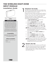
SINTHESI STEEL 2VOICE BUTTON MODULE
WITH EXPANSION Ref. 1158/82 – 1158/84
The Sinthesi Steel button modules with expander are dedicated to the
2VOICE system and integrate some of the functions provided by the
user expansion module Ref. 1083/17. They are used to manage 62
call buttons for up to 64 users in total for each door unit (on the door
unit there are already 2).
The models available are as follows:
Ref. 1158/82 = 2 buttons module
Ref. 1158/84 = 4 buttons module
INSTALLATION
Please refer to the information contained in the chapter “Installation”
present in the products of this section:
Door phone door unit Ref. 1083/64.
MECHANICAL INSTALLATION INSTRUCTIONS
Installation of the button modules
Arrangement of the button modules
Arrangement allowed Arrangement not allowed
•
PUSH BUTTON PANEL SINTHESI STEEL
SINTHESI STEEL 2VOICE BUTTON MODULE WITH EXPANSION Ref. 1158/82 – 1158/84
PUSH BUTTON PANEL SINTHESI STEEL
CONNECTION INSTRUCTIONS
SYSTEMS WITH DOOR PHONE DOOR UNIT Ref. 1083/64
Connection in systems with a maximum of 32 users or maximum
of 8 button modules with expansion unit.
ILL
1158/84
1158/84
1083/64
1758/83
1158/84
1158/84
1158/82
1158/84
1158/84
1158/84
A
A
B B B
B
B
C
D
A
55 cm-long cable provided with the button module with
expansion unit Ref. 1158/82 and /84
B
20 cm-long cable provided with the button module with
expansion unit Ref. 1158/82 and /84
C
20 cm-long cable provided with the outdoor video station Ref.
1083/64 or video door phone system Ref. 1083/63 (60Hz)
D
18 cm-long cable provided with the camera Ref. 1758/83

12
−−−−
sec.3e
2 VOICE - Technical Manual
PUSH BUTTON PANEL
PUSH BUTTON PANEL SINTHESI STEEL
DDA MODULE WITH VOICE MESSAGES Ref. 1158/47
Connection in systems with 33÷64 users (the transformer must be
used Ref. 9000/230)
ILL
1158/84
1158/84
1083/64
9000/230
~0
~12
1758/83
1158/84
1158/84
1158/84
1158/84
1158/84
1158/84
1158/84
1158/84
A
A
B B B
B
B
B
B
C
D
To the other button modules with expansion unit
(total of 16) for a maximum of 62 call buttons
(Note: on the door unit there are already 2)
A
55 cm-long cable provided with the button module with
expansion unit Ref. 1158/82 and /84
B
20 cm-long cable provided with the button module with
expansion unit Ref. 1158/82 and /84
C
20 cm-long cable provided with the outdoor video station Ref.
1083/64 or video door phone system Ref. 1083/63 (60Hz)
D
18 cm-long cable provided with the camera Ref. 1758/83
BUTTONS CONFIGURATION
USER = 2
USER = 3
USER = 0
USER = 1
USER = 4
USER = 5
USER = 6
USER = 7
USER = 8
USER = 9
USER = 62
USER = 63
TECHNICAL CHARACTERISTICS
Absorption (excluding name tag): ................Max 1 mA each module
Absorption of name tags: ........................Max 12,5 mA each module
Tag lighting (directly from door unit): .......................................Max 32
Tag lighting with external transformer Ref.9000/230: ............Max 64
Operating temperature range: .................................. -10 °C ÷ + 50 °C
PUSH BUTTON PANEL SINTHESI STEEL
DDA MODULE WITH VOICE MESSAGES
Ref. 1158/47
The voice messages synthesis module with led Ref. 1158/47 allows
the user to know the system status by means of video and audio
signals.
This module allows to hard of hearing and partially sighted people to
access basic functions using the push button panel.
The system status is shown by the following indications:
a) call in progress: icon with RED light and voice message
“CALL IN PROGRESS”
b) conversation in progress: icon with yellow light
c) the door is open: icon icon with GREEN light and voice message
“DOOR OPEN”
PROGRAMMING AND ADJUSTMENTS
Connector for
connection to
digital system with
provided cable
Terminal pins for
connection to
analog systems
Terminal pins for power
supply with dedicated
transformer
Programming
Dip-switch
Voice message
volume adjustement
System type setting:
Analog system (4+n, coax, 1+1, 5 wires)
Digital system (Bibus, Ipervoice, 2Voice)
(default)

sec.3e
−−−−
13
2 VOICE - Technical Manual
PUSH BUTTON PANEL
PUSH BUTTON PANEL SINTHESI STEEL
DDA MODULE WITH VOICE MESSAGES Ref. 1158/47
Languages of voice messages can be selected with the other 3 dip-
switches:
Italian
Spanish
English
(default)
Greek
French Polish
German
In order to activate the programming changes, unpower the
device and power it again.
DESCRIPTION OF TERMINALS
C1 call tone input/output
SN call tone input/output
9/5 door lock release command input
F audio command input for 1+1 and 5-wire systems
1A audio command input for 4+n and coax systems
- ground reference
~12 12Vac or 12Vdc power supply
~0 power supply ground
TECHNICAL CHARACTERISTICS
Power voltage ................................................................12 V ac or dc
Max. current consumption ...................................... 150 mA @ 12 Vdc
200 mA @ 12 Vac
Voice messages acoustic pressure .............................80 dB at 10 cm
Operating temperature range ............................................ -5 ÷ +45 °C
DOOR LOCK RELEASE DEVICES
INSTALLATION
If it is needed to install devices used to activate the electric lock or
other electric loads, follow the procedure below:
remove the module front panel
fi x the device used to activate the electric lock to the provided
holed front panel
§
–
–
Key device
M3x12 screws provided
with 1158/47 module
Trasponder device
PUSH BUTTON PANEL SINTHESI STEEL

14
−−−−
sec.3e
2 VOICE - Technical Manual
PUSH BUTTON PANEL
HEARING IMPAIRED PEOPLE MODULE
Ref. 1158/48
ILA (Induction Loop Antenna) T-coil module Ref.1158/48 allows hard
of hearing to hear door unit audio conversations with the hearing aid.
The hearing aid must be equipped with a T-magnetic interface.
Set the switch
to T mode
Module with
door unit
T-Coil module
for hard of
hearing people
Button module
20cm max.
INSTALLATION
12 Vdc or Vac
Power supply
To ILA terminal pin
Ref. 1083/64 module
~12
~0
DESCRIPTION OF TERMINALS
ILA ILA two terminal pins to be connected to ILA terminal
~12 12Vac or 12Vdc power supply
~0 power supply ground
A power supply device dedicated to Ref. 1158/48 module is
needed.
CARATTERISTICHE TECNICHE
Power voltage ................................................................12 V ac or dc
Max. current consumption ...................................... 100 mA @ 12 Vdc
200 mA @ 12 Vac
Operating temperature range ............................................ -5 ÷ +45 °C
§
REPERTORY MODULE Ref. 1158/50
Repertory modules are normally used to indicate the house number or
contain other information.
Power terminals ~0 and ~12 to light the unit via LEDs.
The procedure for fi tting repertory tags is the same as that for the
name tags.
Dummy transparent name holder
Final engraved name holder
BLANK MODULE Ref. 1158/59
This module is used to fi ll in spaces which are not used in modular
applications as required.
The same module can be used for other applications, e.g. burglar
alarms and automatic gates.
PUSH BUTTON PANEL SINTHESI STEEL
HEARING IMPAIRED PEOPLE MODULE Ref. 1158/48
REPERTORY MODULE Ref. 1158/50 - BLANK MODULE Ref. 1158/59
PUSH BUTTON PANEL SINTHESI STEEL

sec.3e
−−−−
15
2 VOICE - Technical Manual
PUSH BUTTON PANEL
PUSH BUTTON PANEL SINTHESI STEEL
MODULO REPERTORIO Sch.1158/50 - MODULO CIECO Sch.1158/59
ELENCO PRODOTTI
PUSH BUTTON PANEL SINTHESI STEEL - PRODUCTS LIST
COMPLEMENTARY PRODUCTS LIST
All Sinthesi Steel products, their characteristics and installation
modes are described in “Products Technical Manual - Door Phone
and Video Door Phone system” in the section “Sinthesi Steel Push
Button Panel”.
METAL FLUSH-MOUNTING BOXES
For 1 module Ref. 1158/41
For 2 modules Ref. 1158/42
For 3 modules Ref. 1158/43
For 4 modules Ref. 1158/44
PLASTIC FLUSH-MOUNTING BOXES
For 1 module Ref. 1145/51
For 2 modules Ref. 1145/52
For 3 modules Ref. 1145/53
For 4 modules Ref. 1145/54
FRAMES AND MODULE HOLDERS
For 1 module Ref. 1158/61
For 2 modules Ref. 1158/62
For 3 modules Ref. 1158/63
For 4 modules Ref. 1158/64
WALL-MOUNTED CASING WITH HOOD
For 1 module Ref. 1148/311
For 2 modules Ref. 1148/312
For 3 modules Ref. 1148/313
For 4 modules Ref. 1148/314
For 4 modules (2 module holders with 2 modules) Ref. 1148/324
For 6 modules (2 module holders with 3 modules) Ref. 1148/326
For 9 modules (3 module holders with 2 modules) Ref. 1148/339
RAIN HOODS
For 1 module Ref. 1158/611
For 2 modules Ref. 1158/612
For 3 modules Ref. 1158/613
For 4 modules Ref. 1158/614
For 4 modules (2 module holders with 2 modules) Ref. 1158/624
For 6 modules (2 module holders with 3 modules) Ref. 1158/626
For 9 modules (3 module holders with 2 modules) Ref. 1158/639

16
−−−−
sec.3e
2 VOICE - Technical Manual
PUSH BUTTON PANEL
FLUSH-MOUNTED VERSION
119mm 45mm
H1
125mm
H2
247mm 45mm
H1 H2
254mm
376mm 45mm
H1
H2
383mm
505mm 45mm
H1
H2
512mm
H2
641mm
H1
634mm
45mm
WALL-MOUNTED VERSION
H1 H2
For 1 module 117 mm 127 mm
For 2 modules 207 mm 217 mm
For 3 modules 297 mm 307 mm
For 4 modules 387 mm 397 mm
PUSH BUTTON PANEL SINTHESI STEEL - OVERALL DIMENSIONS
157mm
H3
79mm
59mm
79mm
59mm
79mm
59mm
286mm
H3
416mm
H3
H3 L
For 1 module 152 mm 157 mm
For 2 module s 242 mm 157 mm
For 3 module s 332 mm 157 mm
For 4 modules 422 mm 157 mm
For 4 modules -
2 module holders
242 mm 286 mm
322 mm 286 mm
332 mm 416 mm
For 6 modules -
2 module holders
For 9 modules -
3 module holders
PUSH BUTTON PANEL SINTHESI STEEL
OVERALL DIMENSIONS

sec.3e
−−−−
17
2 VOICE - Technical Manual
PUSH BUTTON PANEL PUSH BUTTON PANEL SINTHESI STEEL - VIDEO DOOR PHONE SYSTEMS
VIDEO DOOR PHONE SYSTEMS
MODULARITY EXAMPLES FOR DIFFERENT SYSTEM WITH Ref. 1158/8x
video door phones
BUTTONS NUMBER
1 2 3 4 5 6 7 8 9 1011121314151617181920212223242526272829303132
Common
products
Door unit with
module
1083/64
11111111111111111111111111111111
Camera 1758/83 1 1 1 1 1 1 1 1 1 1 1 1 1 1 1 1 1 1 1 1 1 1 1 1 1 1 1 1 1 1 1 1
Button modules
with expansions
1158/82 1 1 1 1 1 1 1 1 1 1 1 1 1 1 1 1 1 1 1
1158/84 1 1 2 2 2 2 3 3 3 3 4 4 4 4 5 5 5 5 6 6 6 6 7 7 7 7
Blank module 1158/59 1 1 1 1 1 1 1 1 2 2
Flush-
mounting
Flush
mounting box
1158/41
1158/42 1 1
1158/43 1 1 1 1 2 2 2 2 2 2 2 2 3 3 3 3
1158/44 1 1 1 1 1 2 2 2 2 2 2 2 3 3
Module holders
and frames
1158/61
1158/62 1 1
1158/63 1 1 1 1 2 2 2 2 2 2 2 2 3 3 3 3
1158/64 1 1 1 1 1 2 2 2 2 2 2 2 3 3
Rain hood
1158/611
1158/612 1 1
1158/613 1 1 1 1
1158/614 1 1 1 1
1158/626 1 1 1 1 1 1 1 1
1158/639 1 1 1 1 1 1 1 1 1 1 1 1
Support
wall
Case with hood
(**)
1148/311
1148/312 1 1
1148/313 1 1 1 1
1148/314 1 1 1 1
1148/324
1148/326 1 1 1 1 1 1 1 1
1148/339 1 1 1 1 1 1 1 1 1 1 1 1
1 2 3 4 5 6 7 8 9 10 11 12 13 14 15 16 17 18 19 20 21 22 23 24 25 26 27 28 29 30 31 32
BUTTONS NUMBER
(**) Instead of products for fl ush mounting installation: fl ush mount boxes, frames and module-holder frames and rain hoods.
video door phones
BUTTONS NUMBER
33 34 35 36 37 38 39 40 41 42 43 44 45 46 47 48 49 50 51 52 53 54 55 56 57 58 59 60 61 62 63 64
Common
products
Door unit with
module
1083/64
11111111111111111111111111111111
Camera 1758/83 1 1 1 1 1 1 1 1 1 1 1 1 1 1 1 1 1 1 1 1 1 1 1 1 1 1 1 1 1 1 1 1
Button modules
with expansions
1158/82 1 1 1 1 1 1 1 1 1 1 1 1 1 1 1 1
1158/84 8 8 8 8 9 9 9 9 10 10 10 10 11 11 11 11 12 12 12 12 13 13 13 13 14 14 14 14 15 15 15 15
Blank module 1158/59 2 2 1 1 1 1 2 2 2 2 1 1 1 1 1 1 1 1
Flush-
mounting
Flush
mounting box
1158/43 5 5 5 5 5 5 5 5 5 5 5 5 6 6 6 6 6 6
1158/44 3 3 3 3 3 3 3 3 3 3 4 4 4 4
Module holders
and frames
1158/63 5 5 5 5 5 5 5 5 5 5 5 5 6 6 6 6 6 6
1158/64 3 3 3 3 3 3 3 3 3 3 4 4 4 4
Rain hood
1158/611
1158/612
1158/613
Support
wall
Case with hood
(**)
1148/311
1148/312
1148/313
1148/314
1148/324
1148/326
1148/339
Name holders lighting transformer
✔✔✔✔✔✔✔✔✔✔✔✔✔✔✔✔✔✔✔✔✔✔✔✔✔✔✔✔✔✔✔✔
33 34 35 36 37 38 39 40 41 42 43 44 45 46 47 48 49 50 51 52 53 54 55 56 57 58 59 60 61 62 63 64
BUTTONS NUMBER
PUSH BUTTON PANEL SINTHESI STEEL
VIDEO DOOR PHONE SYSTEMS
MODULARITY EXAMPLES FOR DIFFERENT SYSTEM WITH Ref. 1158/8X

18
−−−−
sec.3e
2 VOICE - Technical Manual
PUSH BUTTON PANEL
PUSH BUTTON PANEL SINTHESI STEEL
VIDEO DOOR PHONE SYSTEMS
MODULARITY EXAMPLES FOR DIFFERENT SYSTEM WITH Ref. 1158/8X
PUSH BUTTON PANEL SINTHESI STEEL - VIDEO DOOR PHONE SYSTEMS
17-18 19-20
1-2 3-4 5-6 7-8 9-10 11-12 13-14 15-16
27-28 29-30 31-32
21-22 23-24 25-26
33-34
35-36 37-38 39-40 41-42
43-44 45-46 47-48

sec.3e
−−−−
19
2 VOICE - Technical Manual
PUSH BUTTON PANEL
PUSH BUTTON PANEL SINTHESI STEEL
VIDEO DOOR PHONE SYSTEMS
MODULARITY EXAMPLES FOR DIFFERENT SYSTEM WITH Ref. 1158/8X
55-56
59-60
49-50 51-52
61-62 63-64
53-54
57-58
PUSH BUTTON PANEL SINTHESI STEEL - VIDEO DOOR PHONE SYSTEMS

20
−−−−
sec.3e
2 VOICE - Technical Manual
PUSH BUTTON PANEL
DOOR PHONE SYSTEMS
MODULARITY EXAMPLES FOR DIFFERENT SYSTEM WITH Ref. 1158/8x
door phones
BUTTONS NUMBER
1 2 3 4 5 6 7 8 9 10 11 12 13 14 15 16 17 18 19 20 21 22 23 24 25 26 27 28 29 30 31 32
Common
products
Door unit with
module
1083/64
11111111111111111111111111111111
Button modules
with expansions
1158/82 1 1 1 1 1 1 1 1 1 1 1 1 1 1 1 1
1158/84 1 1 1 1 2 2 2 2 3 3 3 3 4 4 4 4 5 5 5 5 6 6 6 6 7 7 7 7
Blank module 1158/59 1 1 1 1 1 1 1 1
Flush-
mounting (#)
Flush
mounting box
1158/41 1 1
1158/42 1 1 1 1
1158/43 1 1 1 1 2 2 2 2 2 2 2 2 3 3
1158/44 1 1 1 1 2 2 2 2 2 2 2 2
Module holders
and frames
1158/61 1 1
1158/62 1 1 1 1
1158/63 1 1 1 1 2 2 2 2 2 2 2 2 3 3
1158/64 1 1 1 1 2 2 2 2 2 2 2 2
Rain hood
(*)
1158/611 1 1
1158/612 1 1 1 1
1158/613 1 1 1 1 1
1158/614 1 1 1 1
1158/626 1 1 1 1 1 1 1 1
1158/639 111111111
Support
wall (#)
Case with hood
1148/311 1 1
1148/312 1 1 1 1
1148/313 1 1 1 1 1
1148/314 1 1 1 1
1148/326 1 1 1 1 1 1 1 1
1148/339 111111111
1 2 3 4 5 6 7 8 9 10 11 12 13 14 15 16 17 18 19 20 21 22 23 24 25 26 27 28 29 30 31 32
BUTTONS NUMBER
(#) alternatively; (*) optional
door phones
BUTTONS NUMBER
33 34 35 36 37 38 39 40 41 42 43 44 45 46 47 48 49 50 51 52 53 54 55 56 57 58 59 60 61 62 63 64
Common
products
Door unit with
module
1083/64
11111111111111111111111111111111
Button modules
with expansions
1158/82 1 1 1 1 1 1 1 1 1 1 1 1 1 1 1 1
1158/84 8 8 8 8 9 9 9 9 10 10 10 10 11 11 11 11 12 12 12 12 13 13 13 13 14 14 14 14 15 15 15 15
Blank module 1158/59 2 2 2 2 1 1 1 1 2 2 2 2 1 1 1 1 1 1
Flush-
mounting
Flush
mounting box
1158/43 3 3 5 5 5 5 5 5 5 5 5 5 5 5 6 6
1158/44 3 3 3 3 3 3 3 3 3 3 3 3 4 4 4 4
Module holders
and frames
1158/63 3 3 5 5 5 5 5 5 5 5 5 5 5 5 6 6
1158/64 3 3 3 3 3 3 3 3 3 3 3 3 4 4 4 4
Rain hood
1158/611
1158/612
1158/639 1 1
Support
wall (#)
Case with hood
(**)
1148/311
1148/312
1148/313
1148/314
1148/324
1148/326
1148/339 1 1
Name holders lighting transformer
✔✔✔✔✔✔✔✔✔✔✔✔✔✔✔✔✔✔✔✔✔✔✔✔✔✔✔✔✔✔✔✔
33 34 35 36 37 38 39 40 41 42 43 44 45 46 47 48 49 50 51 52 53 54 55 56 57 58 59 33 34 35 36 37
BUTTONS NUMBER
PUSH BUTTON PANEL SINTHESI STEEL
DOOR PHONE SYSTEMS
MODULARITY EXAMPLES FOR DIFFERENT SYSTEM WITH Ref. 1158/8X
PUSH BUTTON PANEL SINTHESI STEEL - DOOR PHONE SYSTEMS
/