Page is loading ...

sec.3a
−−−−
1
2 VOICE - Technical Manual
SECTION 3A
(REv. B)
PUSH BUTTON PANEL
Download from www.urmet.com Technical Manuals area.
SECTION CONTENTS
SINTHESI PUSH BUTTON PANEL 2
CAMERA MODULE AND DOOR UNIT WITH 2 BUTTONS ..............2
Features ........................................................................................2
Structure .......................................................................................2
Terminals pins description ...........................................................3
Technical characteristics ..............................................................3
Default programming ....................................................................3
Operation ......................................................................................3
Camera lens orientation adjusting ................................................ 4
Audio adjusting .............................................................................4
Name holders lighting ...................................................................4
DOOR UNIT MODULE WITH 2 BUTTONS .......................................5
Features ........................................................................................5
Structure .......................................................................................5
Terminals pins description ...........................................................5
Technical characteristics ..............................................................6
Default programming ....................................................................6
Operation ......................................................................................6
Audio adjusting .............................................................................6
Name holders lighting ...................................................................6
1-button front unit ........................................................................7
16-USER EXPANSION MODULE Ref.1038/17 ................................8
Connection example.....................................................................8
Terminals pins description ...........................................................8
Technical characteristics ..............................................................8
PRODUCT LISTS ..............................................................................8
INSTALLATION .................................................................................9
OVERALL DIMENSIONS ................................................................12
MODULARITY EXAMPLES ............................................................. 13
CONFIGURATION ..........................................................................23
ASSOCIATION OF DOOR UNITS BUTTONS TO USERS .............. 24
Main door units ...........................................................................24
Secondary door units .................................................................25
OPTIONAL PROGRAMMING .........................................................26
Auto-on function on surveillance cameras ................................. 26
Button conguration for special function ...................................26
PROGRAMMING DATA DELETING ...............................................26

2
−−−−
sec.3a
2 VOICE - Technical Manual
PUSH BUTTON PANEL
SINTHESI PUSH BUTTON PANEL
The system consists of anodized aluminium prole modular elements
and is composed by modules which can be tted in specic module
holder frames.
Using suitable spacers, ush mounting boxes can be combined
to realize any type of push button panels, reducing the number of
components and cards managed in stocks. This is to wholesaler’s
and installer’s advantage.
Module installation is easy, thanks to pre-wired connections on
modules and to rising clamp removable terminal blocks.
All Sinthesi products, their characteristics and installation modes are
described in “Products Technical Manual – Door Phone and Video
Door Phone systems” in the section “Sinthesi Push Button Panel”.
CAMERA MODULE AND DOOR UNIT WITH 2
BUTTONS Ref. 1083/72 AND Ref. 1083/71
FEATURES
Installation on Sinthesi module holder frames with 2 modules.
Two pre-wired call buttons.
4 expansion modules (connected in series) can be connected, up to
64 user buttons max. for each door unit.
Connection of 16-user expansion module Ref. 1038/17 or Ref.
1083/17 with connector.
Up to 4 main call stations and up to two secondary call stations can
be connected for each column.
Fixed focus colour camera with embedded lens and shutter.
Lens orientation can be adjusted.
Embedded illuminator, that can be excluded under sufcient
lighting conditions.
Codes sequences can be assigned to call buttons with dip-switch.
All the programming procedure can be performed with dip-switch.
Off-hook waiting time: 60 seconds (system busy).
The guaranteed communication time can be programmed with
rotary-switch up to 70 seconds (system busy).
Max. conversation time starting when the handset is picked up: 10
minutes.
Tone for conrming call sending and conversation end.
Video-audio signals of system busy.
Pedestrian electric lock command actuator. Programmable timing
with rotary-switch from 1 to 90 seconds.
Driveway electric lock command actuator with clean contact.
Electric lock management: Free or Secret.
Circuitry for electric lock activation with entrance hall button.
Input for open door sensor.
Trimmer for adjusting loudspeaker and microphone audio level.
Management of two external coax video inputs for surveillance
cameras, if present (Ref. 1083/72 only).
Relay box driving for cyclic control of several video surveillance
cameras (Ref. 1083/72 only).
Output for power supply of name holders lighting (up to 32 buttons
with the power supply unit Ref. 1083/20).
Audio repeater device for hard of hearing people (Ref. 1083/72
only).
•
•
•
•
•
•
•
•
•
•
•
•
•
•
•
•
•
•
•
•
•
•
•
•
•
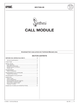
STRUCTURE
FRONT VIEW
2
4
5
6
3
1
REAR VIEW
7
8
9
10
12
13
14
11
1. Camera
2. Signalling yellow led
3. Microphone
4. Pre-wired buttons
5. Name holders
6. Loudspeaker
7. Rotary-switch for pedestrian door lock release activation time
8. Auxiliary settings dip-switch
9. Identication code dip-switch
10. Busy time rotary-switch
11. Connector for expansion module
12. Loudspeaker volume adjustment
13. Microphone volume adjustment
14. Terminal blocks
SINTHESI PUSH BUTTON PANEL
CAMERA MODULE AND DOOR UNIT WITH 2 BUTTONS
SINTHESI PUSH BUTTON PANEL

sec.3a
−−−−
3
2 VOICE - Technical Manual
PUSH BUTTON PANEL
TERMINAL PINS DESCRIPTION
]
LINE Incoming Bus line
SE+ Positive for pedestrian electric lock activation
SE- Negative for pedestrian electric lock activation
]
A
V3 Surveillance camera 1 signal
}
Ref. 1083/72
only
V5
Reference for surveillance camera 1
signal
]
B
V3
Surveillance camera 2 signal / video
switch
V5
Reference for surveillance camera 2 /
video switch
]
ILA Hard of hearing device output
]
SE2 Driveway electric lock activation
T+ Command for video switch
}
Ref. 1083/72
only
T- Reference for video switch
CT Reference for PA and SP
PA Entrance hall button
SP Open door sensor (*)
]
ILL Power supply for name holders lighting
-
}
Do not use
+
(*) the terminal pin SP is connected by default to the terminal pin
CT; to connect the normally close door sensor (with closed
door), remove the jumper.
TECHNICAL CHARACTERISTICS
Power supply voltage (LINE): 36 – 48vdc
Standby current consumption: 45mA max
Max. current consumption: 250mA max
(video call and name holders on)
Name holders lighting ILL output: 11 – 13,8vdc max 200mA
Lock output SE+ and SE-: 22 – 24vdc max 200mA
SE2 switched load: 300mA 125v Max
Operating temperature range: -10°C ÷ + 50°C
Compliant with: EN 61000-6-3, EN 61000-6-1
DEFAULT PROGRAMMING
All cameras are congured in factory as follows:
Call station type: main
Secondary number: 0
Door lock release: free
Interruption: Not enabled
Camera illuminators: on
Guaranteed comunication time rotary: 30 s (pos 3)
Door lock release rotary: 1 s (pos 0)
Door unit number: 0
Power supply: from the line (LINE)
OPERATION
CALLS
Up to 64 users max. can be called by pressing the respective buttons
of the push button panel associated to the camera.
After pressing the call button, the two following cases can occur:
The line is free: the door unit emits a conrmation tone and the call
is sent to the selected user.
The line is busy: the door unit emits an alert tone and the yellow led
on the front blinks (when the busy time is elapsed, the call must be
sent again).
If in the system there is a concierge switchboard in “Day” mode,
all the calls performed from the main call stations are intercepted
and managed by the switchboard.
PEDESTRIAN ELECTRIC LOCK ACTIvATION
Door units are provided with two terminal pins for pedestrian electric
lock activation (SE-, SE+). The electric lock is activated in the following
cases:
Each time the entrance hall button is pressed (terminal pins PA,
CT).
After receiving a door lock release command from an apartment
station, according to the conguration of the dip-switch used
to congure the operating mode “free” or “secret” (see section
“2VOICE system”, paragraph “Call stations features”).
When the call is sent to an apartment station which is provided with
“automatic door lock release” feature and this function is active.
If electric locks to be activated need special timing, the rotary switch
“DOOR TIME” must be adjusted.
During electric lock activation, additional name holders, if
powered by door unit terminal pins ILL, switch off.
DRIvEWAY DOOR LOCK RELEASE MANAGEMENT
Door units are provided with two terminal pins (SE2) connected to the
contacts of a normally open relay, that can be used to command a
gate opening control panel. The relay is activated for 1 second after
receiving a driveway door lock release command from an apartment
station, according to the congured operation mode, “free” or
“secret”, as for the pedestrian electric lock.
This relay is NOT suitable to manage directly power loads, but
can only be used as command relay.
•
•
§
•
•
•
§
§
SINTHESI PUSH BUTTON PANEL
CAMERA MODULE AND DOOR UNIT WITH 2 BUTTONS
SINTHESI PUSH BUTTON PANEL

4
−−−−
sec.3a
2 VOICE - Technical Manual
PUSH BUTTON PANEL
CAMERA LENS ORIENTATION ADJUSTING
After installation, camera orientation can be adjusted according to the
position of the camera and the captured subject. This operation can
be performed manually, after removing the frame and the extractable
front unit. Move the articulated stand on the front side. It is not
necessary to fold down the frame or use special tools.
vIEWING ANGLES
Camera moving angles regarding the centered position are the
following:
VERTICAL +10 ÷-15° HORIZONTAL +10 ÷-10°
HORIZONTAL
VERTICAL
Measures in cm
AUDIO ADJUSTMENT
Audio levels are trimmed in factory, so they don’t need to be changed
in most installations.
If it is necessary to change them, use a screwdriver on the suitable
adjusting points.
NAME HOLDERS LIGHTING
If the call station has more than 32 name holders, an additional
transformer must be used for button modules lighting.
In this case, the terminal pins “ILL” of the call station must not be
connected to the button modules.
Call station with
32 name holders max.
Call station with more than
32 name holders
To expansion
modules
To expansion
modules
To next button
modules
To next button
modules
2
Line~
8 8
2
TC
~0
~12
~
~
~12
G/T
~0
U1
G/T
U3
U2
~12
~0
U4
CT
V3
SE+
T+
PA
T-
LINE
V5
V3
SP
V5
SE-
SE2
ILL
ILA
A
B
EXP
TC
~12
G/T
~0
U1
G/T
U3
U2
~12
~0
U4
CT
V3
SE+
T+
PA
T-
LINE
V5
V3
SP
V5
SE-
SE2
ILL
ILA
A
B
EXP
Name holders
lighting
transformer
The transformer Ref. 9000/230 can provide 11,2 W power, that is up
to 64 name holders max.
The number of name holders could be reduced according to
distance and section of the used cable.
§
SINTHESI PUSH BUTTON PANEL
CAMERA MODULE AND DOOR UNIT WITH 2 BUTTONS
SINTHESI PUSH BUTTON PANEL

sec.3a
−−−−
5
2 VOICE - Technical Manual
PUSH BUTTON PANEL
SINTHESI PUSH BUTTON PANEL
DOOR UNIT MODULE WITH 2 BUTTONS
DOOR UNIT MODULE WITH 2 BUTTONS Ref.
1083/7 AND Ref. 1083/5
FEATURES
Installation on 2-module Sinthesi module holder frames.
Two pre-wired call buttons.
4 expansion modules can be installed (connected in series), up to
64 user buttons max. for each door unit.
Connection of 16-user expansion module Ref. 1038/17 or Ref.
1083/17 with connector.
Up to 4 main call stations and up to 2 secondary call stations can
be connected for each column.
Code sequences can be assigned to call buttons with the dip-
switch.
All the programming procedure can be performed with dip-switch.
Off-hook waiting time: 60 seconds (system busy).
Guaranteed communication time can be programmed with rotary-
switch up to 70 seconds (system busy).
Max. conversation time starting when the handset is picked up: 10
minutes.
Tone for conrming call sending and conversation end.
Video-audio signals of system busy.
Pedestrian electric lock command actuator. Programmable timing
with rotary-switch from 1 to 90 seconds.
Driveway electric lock command actuator with clean contact.
Electric lock management: Free or Secret.
Circuitry for electric lock activation with entrance hall button.
Input for open door sensor.
Trimmer for adjusting loudspeaker and microphone audio level.
Management of two external coax video inputs for surveillance
cameras, if present (Ref. 1083/7 only).
Relay box driving for cyclic control of several video surveillance
cameras (Ref. 1083/7 only).
Output for power supply of name holders lighting (up to 32 buttons
with the power supply unit Ref. 1083/20).
Audio repeater device for hard of hearing people (Ref. 1083/7
only).
STRUCTURE
FRONT VIEW
1
3
4
5
2
•
•
•
•
•
•
•
•
•
•
•
•
•
•
•
•
•
•
•
•
•
•
REAR VIEW
6
7
8
9
11
12
13
10
1. Signalling yellow led
2. Microphone
3. Pre-wired buttons
4. Name holders
5. Loudspeaker
6. Rotary-switch for pedestrian door lock release activation time
7. Auxiliary settings dip-switch
8. Identication code dip-switch
9. Busy time rotary-switch
10. Connector for expansion module
11. Loudspeaker volume adjustment
12. Microphone volume adjustment
13. Terminal blocks
TERMINAL PINS DESCRIPTION
]
LINE Incoming Bus line
SE+ Positive for pedestrian electric lock activation
SE- Negative for pedestrian electric lock activation
]
A
V3 Surveillance camera 1 signal
}
Ref. 1083/7
only
V5
Reference for surveillance camera 1
signal
]
B
V3
Surveillance camera 2 signal / video
switch
V5
Reference for surveillance camera 2 /
video switch
]
ILA Hard of hearing device output
]
SE2 Driveway electric lock activation
T+ Command for video switch
}
Ref. 1083/7
only
T- Reference for video switch
CT Reference for PA and SP
PA Entrance hall button
SP Open door sensor (*)
]
ILL Power supply for name holders lighting
-
}
Do not use
+
(*) the terminal pin SP is connected by default to the terminal pin
CT; to connect the normally closed door sensor (with closed
door), remove the jumper.
If a camera is connected to Ref. 1083/7 terminal pins V3A and
V5A, the same features as those of a camera module with a door
unit will be available. These features will not be available if no
cameras are connected to terminal pins V3B and V5B.
§
SINTHESI PUSH BUTTON PANEL

6
−−−−
sec.3a
2 VOICE - Technical Manual
PUSH BUTTON PANEL
SINTHESI PUSH BUTTON PANEL
DOOR UNIT MODULE WITH 2 BUTTONS
TECHNICAL CHARACTERISTICS
Power supply voltage (LINE): 36 – 48vdc
Standby current consumption: 45mA max
Max. current consumption: 220mA max
(video call and name holders on)
Name holders lighting ILL output: 11 – 13,8vdc max 200mA
Lock output SE+ and SE-: 22 – 24vdc max 200mA
SE2 switched load: 300mA 125v Max
Operating temperature range: -10°C ÷ + 50°C
Compliant with: EN 61000-6-3, EN 61000-6-1
DEFAULT PROGRAMMING
All door unit modules are congured in factory as follows:
Call station type: main
Secondary number: 0
Door lock release: free
Interruption: Not enabled
Guaranteed comunication time rotary: 30 s (pos 3)
Door lock release rotary: 1 s (pos 0)
Door unit number: 0
Power supply: from the line (LINE)
OPERATION
CALLS
Up to 64 users max. can be called by pressing the respective buttons
of the push button panel associated to the door unit module.
After pressing the call button, the two following cases can occur:
The line is free: the door unit emits a conrmation tone and the call
is sent to the selected user.
The line is busy: the door unit emits an alert tone and the yellow led
on the front blinks (when the busy time is elapsed, the call must be
sent again).
If in the system there is a concierge switchboard in “Day” mode,
all the calls performed from the main call stations are intercepted
and managed by the switchboard.
PEDESTRIAN ELECTRIC LOCK ACTIvATION
Door units are provided with two terminal pins for pedestrian electric
lock activation (SE-, SE+). The electric lock is activated in the following
cases:
Each time the entrance hall button is pressed (terminal pins PA,
CT).
After receiving a door lock release command from an apartment
station, according to the conguration of the dip-switch used
to congure the operating mode “free” or “secret” (see section
“2VOICE system”, paragraph “Call stations features”).
When the call is sent to an apartment station which is provided with
“automatic door lock release” feature and this function is active.
If electric locks to be activated need special timing, the rotary switch
“DOOR TIME” must be adjusted.
During electric lock activation, additional name holders, if
powered by door unit terminal pins ILL, switch off.
DRIvEWAY DOOR LOCK RELEASE MANAGEMENT
Door units are provided with two terminal pins (SE2) connected to the
contacts of a normally open relay, that can be used to command a
gate opening control panel. The relay is activated for 1 second after
receiving a driveway door lock release command from an apartment
station, according to the congured operation mode, “free” or
•
•
§
•
•
•
§
“secret”, as for the pedestrian electric lock.
This relay is NOT suitable to manage directly power loads, but
can only be used as command relay.
AUDIO ADJUSTMENT
Audio levels are trimmed in factory, so they don’t need to be changed
in most installations.
If it is necessary to change them, use a screwdriver on the suitable
adjusting points.
NAME HOLDERS LIGHTING
If the call station has more than 32 name holders, an additional
transformer must be used for button modules lighting.
In this case, the terminal pins “ILL” of the call station must not be
connected to the button modules.
Call station with
32 name holders max.
Call station with more than
32 name holders
To expansion
modules
To expansion
modules
To next button
modules
To next button
modules
2
Line~
8 8
2
~0
~12
~
~
~12
G/T
~0
U1
G/T
U3
U2
~12
~0
U4
CT
V3
SE+
T+
PA
T-
LINE
V5
V3
SP
V5
SE-
SE2
ILL
ILA
A
B
EXP
~12
G/T
~0
U1
G/T
U3
U2
~12
~0
U4
CT
V3
SE+
T+
PA
T-
LINE
V5
V3
SP
V5
SE-
SE2
ILL
ILA
A
B
EXP
Name holders
lighting
transformer
The transformer Ref. 9000/230 can provide 11,2 W power, that is up
to 64 name holders max.
The number of name holders could be reduced according to
distance and section of the used cable.
§
§
SINTHESI PUSH BUTTON PANEL

sec.3a
−−−−
7
2 VOICE - Technical Manual
PUSH BUTTON PANEL
SINTHESI PUSH BUTTON PANEL
1-BUTTON FRONT UNIT
1-BUTTON FRONT UNIT
For call station with 1 button, the front unit Ref. 1745/107 must be
bought and installed as follows:
Installation modes are the same as for modules with camera and
door unit modules.
Ref. 1745/107
In this case, if the button is pressed, the apartment station with
user code CODE=1 will be called.
If the module is provided with rmware version 3.1 or higher,
perform the following programming procedure to call the
apartment station with code 0.
ASSIGNING CODE 0 TO THE BUTTON
1. Enter in programming mode by setting the rotary switch DOOR
TIME to position 8 and the rotary switch CONV TIME to position
9. The call station will emit 2 beeps each second to indicate the
programming state.
2. Press the call station button. The module will emit a long beep to
indicate that programming has been successful.
USER 0
Beeep
3. Restore the rotary switches original position to exit from the
programming mode.
§
§
FACTORY CODES RESTORE
To restore the user code assigned to the button, follow the procedure
below:
1. Enter in programming mode by setting the rotary switch DOOR
TIME to position 8 and the rotary switch CONV TIME to position
9. The call station will emit 2 beeps each second to indicate the
programming state.
2. Press the button in the upper side of the call station. The module
will emit a long beep to indicate that programming has been
successful.
USER 0
Beeep
USER 1
3. Set the rotary switches to the correct position to exit from the
programming mode.
SINTHESI PUSH BUTTON PANEL

8
−−−−
sec.3a
2 VOICE - Technical Manual
PUSH BUTTON PANEL
SINTHESI PUSH BUTTON PANEL
16-USER EXPANSION MODULE Ref. 1038/17
16-USER EXPANSION MODULE Ref. 1038/17
Terminal pins
for user buttons
To the
door unit
The expansion module allows to add 16 user buttons to the door
unit.
Place the device in the push button panel as shown in the following
gures.
Connect the user buttons and connect the device to the door unit
or to other expansion modules, if present, with the suitable cable,
respecting connection direction and passages in ush mounting
boxes.
Ref. 1038/17
Screw the device on the ush mounting box bottom, near buttons
modules or blind modules or directory.
CONNECTION EXAMPLE
U4
U3
U2
U1
G/T
~12
~0
~0
~12
G/T
ILL
ILA
T+
T-
V3
V5
A
V3
V5
B
SE2
LINE
EXP
CT
PA
SP
SE+
SE-
Output
Input
P16
P15
C
P14
P13
P12
P11
P10
P9
P1
P2
C
P3
P4
P5
P6
P7
P8
U4
U3
U2
U1
G/T
~12
~0
~0
~12
G/T
U4
U3
U2
U1
G/T
~12
~0
~0
~12
G/T
U4
U3
U2
U1
G/T
~12
~0
~0
~12
G/T
To next expansion
modules
To next button
modules
Expansion
module
TERMINAL PINS DESCRIPTION
C Reference ground
P1÷P16 User buttons
TECHNICAL CHARACTERISTICS
Current consumption: 1mA Max
Current in user button: ~1mA
Operating temperature range: +0°C ÷ +50°C
Humidity: 90% UR a 30 °C
PRODUCT LISTS
All Sinthesi products, their characteristics and installation modes are
described in “Products Technical Manual - Door Phone and Video
Door Phone system” in the section “Sinthesi Push Button Panel”
BUTTONS MODULES AND DIRECTORY
With 1 button Ref. 1145/11
With 2 buttons Ref. 1145/12
With 3 buttons Ref. 1145/13
With 4 buttons Ref. 1145/14
With 4 Double buttons Ref. 1145/18
Directory module Ref. 1145/50
Blind module Ref. 1145/59
FLUSH MOUNTING BOXES
For 2 modules Ref. 1145/52
For 3 modules Ref. 1145/53
For 4 modules Ref. 1145/54
FRAMES AND MODULE HOLDERS
For 2 modules Ref. 1145/62
For 3 modules Ref. 1145/63
For 4 modules Ref. 1145/64
EMBEDDING FRAMES
For 2 modules Ref. 1145/712
For 3 modules Ref. 1145/713
For 4 modules Ref. 1145/714
For 4 modules (2 module holders with 2 modules) Ref. 1145/724
For 6 modules (2 module holders with 3 modules) Ref. 1145/726
For 8 modules (2 module holders with 4 modules) Ref. 1145/728
For 9 modules (3 module holders with 3 modules) Ref. 1145/739
For 12 modules (3 module holders with 4 modules) Ref. 1145/732
RAIN HOODS
For 2 modules Ref. 1145/612
For 3 modules Ref. 1145/613
For 4 modules Ref. 1145/614
For 4 modules (2 module holders with 2 modules) Ref. 1145/624
For 6 modules (2 module holders with 3 modules) Ref. 1145/626
For 8 modules (2 module holders with 4 modules) Ref. 1145/628
For 9 modules (3 module holders with 3 modules) Ref. 1145/639
For 12 modules (3 module holders with 4 modules) Ref. 1145/632
HOODED HOUSINGS
For 2 modules Ref. 1145/312
For 3 modules Ref. 1145/313
For 4 modules Ref. 1145/314
For 4 modules (2 module holders with 2 modules) Ref. 1145/324
For 6 modules (2 module holders with 3 modules) Ref. 1145/326
For 8 modules (2 module holders with 4 modules) Ref. 1145/328
For 9 modules (3 module holders with 3 modules) Ref. 1145/339
For 12 modules (3 module holders with 4 modules) Ref. 1145/332
HOODED HOUSINGS FOR SEMI-FLUSH MOUNTING IN GATE
PILLAR
For 2 modules Ref. 1145/342
POSTALBOXES
For 2 vertical modules Ref. 1145/42
SINTHESI PUSH BUTTON PANEL

sec.3a
−−−−
9
2 VOICE - Technical Manual
PUSH BUTTON PANEL
SINTHESI PUSH BUTTON PANEL
INSTALLATION
INSTALLATION
It is suggested to install the modules at the height shown below,
according to the system to be realized.
However, for complex systems with several modules, for a correct
installation consider the height shown in the gure to x the camera. If
the system is a door phone, height refers to the door unit.
Before installing the ush mounting box (single or coupled with other
ones), prepare the hole (at the bottom or at the sides) for the passage
of connection wires.
Flush mounting boxes can be assembled with suitable spacers, also
used as wire hole.
If no accessories are included in ush mounting version, an unlimited
number of ush mounting boxes can be combined. In case of systems
also composed by embedding frames or rain hoods, the max. number
of boxes to be combined is 3; the boxes are joined on the longest
side.
All spacers are empty, to allow the passage of wires from a box to
another one.
Arrange the ush mounting boxes and follow the instructions below:
Install the ush mounting box: it must not jut out of the wall.
Mount the module holder.
Mount the modules on the module holder.
•
•
•
SINTHESI PUSH BUTTON PANEL

10
−−−−
sec.3a
2 VOICE - Technical Manual
PUSH BUTTON PANEL
SINTHESI PUSH BUTTON PANEL
INSTALLATION
Fold down the module holder and connect wires.
Set the dip-switches according to instructions in the section
“System installation and activation”.
Adjust the correct perpendicularity of the push button panel.
Close the module holder by fastening screws A.
Fasten screws A
•
•
•
•
Adjust camera orientation.
Fit the name holders.
Engraving side
Blank tag
Place the frame on the module holder.
Fasten screws B on screws A.
•
•
•
•
SINTHESI PUSH BUTTON PANEL

sec.3a
−−−−
11
2 VOICE - Technical Manual
PUSH BUTTON PANEL
SINTHESI PUSH BUTTON PANEL
INSTALLATION
SINTHESI PUSH BUTTON PANEL
The blue headers Ref. 1145/65 may be used to customise the
panel (the kit also comprises blue name tags).
§

12
−−−−
sec.3a
2 VOICE - Technical Manual
PUSH BUTTON PANEL
SINTHESI PUSH BUTTON PANEL - OvERALL DIMENSIONS
FLUSH MOUNTING vERSION
Values H1= 204, 294, 384 concerning ush mounting box height and values H2= 209, 299, 389 concerning the total height, are referred to
versions composed by 2, 3, 4 modules.
WALL MOUNTING vERSION
Values H3 concerning the total height can change according to the number of modules that can be included in the housing.
§
§
SINTHESI PUSH BUTTON PANEL
OvERALL DIMENSIONS

sec.3a
−−−−
13
2 VOICE - Technical Manual
PUSH BUTTON PANEL
SINTHESI PUSH BUTTON PANEL
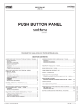
MODULARITY EXAMPLES FOR DIFFERENT SYSTEM DIMENSIONS
(vIDEO DOOR PHONE SYSTEMS)
NUMBER OF BUTTONS
Video door phone
1 2 3 4 5 6 7 8 9 10 11 12 13 14 15 16 17 18 19 20 21 22 23 24 25 26 27 28 29 30 31 32
1145/11
1 1 1 1 1 1 1 1
1145/12
1 1 1 1 1 1 1 1
1145/13
1 1 1 1 1 1 1
1145/14
1 1 1 1 2 2 2 2 3 3 3 3 4 4 4 4 5 5 5 5 6 6 6 6 7 7 7
1145/59
1 1 1 1 1 1 1 1 2 2
Button
modules
and
directory
Camera
modules
with door
unit
1083/72
or
1083/71
1 1 1 1 1 1 1 1 1 1 1 1 1 1 1 1 1 1 1 1 1 1 1 1 1 1 1 1 1 1 1 1
Expansion
module
1038/17
1 1 1 1 1 1 1 1 1 1 1 1 1 1 1 1 2 2 2 2 2 2 2 2 2 2 2 2 2 2
Common
products
1-button
front unit
1745/107
1
1145/52
1 1
1145/53
1 1 1 1 2 2 2 2 2 2 2 2 3 3 3 3
Flush
mounting
box
1145/54
1 1 1 1 2 2 2 2 2 2 2 2 3 3
1145/62
1 1
1145/63
1 1 1 1 2 2 2 2 2 2 2 2 3 3 3 3
Module
holders and
frames
1145/64
1 1 1 1 2 2 2 2 2 2 2 2 3 3
1145/712
1 1
1145/713
1 1 1 1
1145/714
1 1 1 1
1145/726
1 1 1 1 1 1 1 1
1145/728
1 1 1 1 1 1 1 1
1145/739
1 1 1 1
Embedding
frame (°)
1145/732
1 1
1145/612
1 1
1145/613
1 1 1 1
1145/614
1 1 1 1
1145/626
1 1 1 1 1 1 1 1
1145/628
1 1 1 1 1 1 1 1
1145/639
1 1 1 1
Flush
mounting (#)
Rain hood (°)
1145/632
1 1
1145/312
1 1
1145/313
1 1 1 1
1145/314
1 1 1 1
1145/326
1 1 1 1 1 1 1 1
1145/328
1 1 1 1 1 1 1 1
1145/339
1145/342
1 1 1 1
Hooded
housing (§)
1145/332
1 1
Wall
mounting (#)
Postalbox (§) 1145/42
1 1
1 1
Semi-flush
mounting pillar
(#)
Housing
1 2 3 4 5 6 7 8 9 10 11 12 13 14 15 16 17 18 19 20 21 22 23 24 25 26 27 28 29 30 31 32
NUMBER OF BUTTONS
(#); (§) alternative
(°) optional, alternative
SINTHESI PUSH BUTTON PANEL - vIDEO DOOR PHONE SYSTEMS

14
−−−−
sec.3a
2 VOICE - Technical Manual
PUSH BUTTON PANEL
SINTHESI PUSH BUTTON PANEL
MODULARITY EXAMPLES FOR DIFFERENT SYSTEM DIMENSIONS
(vIDEO DOOR PHONE SYSTEMS)
NUMBER OF BUTTONS
33 34 35 36 37 38 39 40 41 42 43 44 45 46 47 48 49 50 51 52 53 54 55 56 57 58 59 60 61 62 63 64
1145/11
1 1 1 1 1 1 1 1
1145/12
1 1 1 1 1 1 1 1
1145/13
1 1 1 1 1 1 1 1
1145/14
7 8 8 8 8 9 9 9 9 10 10 10 10 11 11 11 11 12 12 12 12 13 13 13 13 14 14 14 14 15 15 15
1145/59
1 1 1 1 1 1 1 1 1 1 1 1 1 1 1 1 1 1
1145/50
1 1 1 1 1 1
1083/72
or
1083/71
1 1 1 1 1 1 1 1 1 1 1 1 1 1 1 1 1 1 1 1 1 1 1 1 1 1 1 1 1 1 1 1
1038/17
2 2 3 3 3 3 3 3 3 3 3 3 3 3 3 3 3 3 4 4 4 4 4 4 4 4 4 4 4 4 4 4
1145/52
1145/53
5 5 5 5 5 5 5 5 5 5 5 5 6 6 6 6 6 6
1145/54
3 3 3 3 3 3 3 3 3 3 4 4 4 4
1145/62
1145/63
5 5 5 5 5 5 5 5 5 5 5 5 6 6 6 6 6 6
1145/64
3 3 3 3 3 3 3 3 3 3 4 4 4 4
1145/732
1145/632
1 1 1 1 1 1 1 1 1 1
1 1 1 1 1 1 1 1 1 1
1145/332
1 1 1 1 1 1 1 1 1 1
33 34 35 36 37 38 39 40 41 42 43 44 45 46 47 48 49 50 51 52 53 54 55 56 57 58 59 60 61 62 63 64
NUMBER OF BUTTONS
Video door phone
Button
modules
and
directory
Camera
modules
with door
unit
Expansion
module
Common
products
Flush
mounting
box
Module
holders and
frames
Embedding
frame (°)
Flush
mounting (#)
Rain hood (°)
Hooded
housing
Wall
mounting (#)
Name holders lighting transformer
(#) alternative
(°) optional, alternative
SINTHESI PUSH BUTTON PANEL - vIDEO DOOR PHONE SYSTEMS

sec.3a
−−−−
15
2 VOICE - Technical Manual
PUSH BUTTON PANEL
SINTHESI PUSH BUTTON PANEL
MODULARITY EXAMPLES FOR DIFFERENT SYSTEM DIMENSIONS
(vIDEO DOOR PHONE SYSTEMS)
0
11
17
1615141312
23
2221201918
28
27
262524
32
31
3029
SINTHESI PUSH BUTTON PANEL - vIDEO DOOR PHONE SYSTEMS

16
−−−−
sec.3a
2 VOICE - Technical Manual
PUSH BUTTON PANEL
SINTHESI PUSH BUTTON PANEL
MODULARITY EXAMPLES FOR DIFFERENT SYSTEM DIMENSIONS
(vIDEO DOOR PHONE SYSTEMS)
33
45
34
36
35 37
39
38
40
41
42
43 44
46 47 48
5049 51
52
54
53
SINTHESI PUSH BUTTON PANEL - vIDEO DOOR PHONE SYSTEMS

sec.3a
−−−−
17
2 VOICE - Technical Manual
PUSH BUTTON PANEL
SINTHESI PUSH BUTTON PANEL
MODULARITY EXAMPLES FOR DIFFERENT SYSTEM DIMENSIONS
(vIDEO DOOR PHONE SYSTEMS)
56
59
55 57
58
62 63
60
61
64
SINTHESI PUSH BUTTON PANEL - vIDEO DOOR PHONE SYSTEMS

18
−−−−
sec.3a
2 VOICE - Technical Manual
PUSH BUTTON PANEL
SINTHESI PUSH BUTTON PANEL
MODULARITY EXAMPLES FOR DIFFERENT SYSTEM DIMENSIONS
(DOOR PHONE SYSTEMS)
1 2 3 4 5 6 7 8 9 10 11 12 13 14 15 16 17 18 19 20 21 22 23 24 25 26 27 28 29 30 31 32
1145/11
1 1 1 1 1 1 1 1
1145/12
1 1 1 1 1 1 1 1
1145/13
1 1 1 1 1 1 1
1145/14
1 1 1 1 2 2 2 2 3 3 3 3 4 4 4 4 5 5 5 5 6 6 6 6 7 7 7
1145/59
1 1 1 1 1 1 1 1 2 2
1083/7 or
1083/5
1 1 1 1 1 1 1 1 1 1 1 1 1 1 1 1 1 1 1 1 1 1 1 1 1 1 1 1 1 1 1 1
1038/17
1 1 1 1 1 1 1 1 1 1 1 1 1 1 1 1 2 2 2 2 2 2 2 2 2 2 2 2 2 2
1745/107
1
1145/52
1 1
1145/53
1 1 1 1 2 2 2 2 2 2 2 2 3 3 3 3
1145/54
1 1 1 1 2 2 2 2 2 2 2 2 3 3
1145/62
1 1
1145/63
1 1 1 1 2 2 2 2 2 2 2 2 3 3 3 3
1145/64
1 1 1 1 2 2 2 2 2 2 2 2 3 3
1145/712
1 1
1145/713
1 1 1 1
1145/714
1 1 1 1
1145/726
1 1 1 1 1 1 1 1
1145/728
1 1 1 1 1 1 1 1
1145/739
1 1 1 1
1145/732
1 1
1145/612
1 1
1145/613
1 1 1 1
1145/614
1 1 1 1
1145/626
1 1 1 1 1 1 1 1
1145/628
1 1 1 1 1 1 1 1
1145/639
1 1 1 1
1145/632
1 1
1145/312
1 1
1145/313
1 1 1 1
1145/314
1 1 1 1
1145/326
1 1 1 1 1 1 1 1
1145/328
1 1 1 1 1 1 1 1
1145/339
1 1 1 1
1145/332
1 1
Postalbox (§) 1145/42
1 1
1145/342
1 1
1 2 3 4 5 6 7 8 9 10 11 12 13 14 15 16 17 18 19 20 21 22 23 24 25 26 27 28 29 30 31 32
NUMBER OF BUTTONS
NUMBER OF BUTTONS
Door phone
Button
modules
and
directory
Modules
with door
unit
Expansion
module
Common
products
1-button
front unit
Flush
mounting
box
Module
holders and
frames
Embedding
frame (°)
Flush
mounting (#)
Rain hood (°)
Hooded
housing (§)
Wall
mounting (#)
Semi-flush
mounting pillar
(#)
Housing
(#); (§) alternative
(°) optional, alternative
SINTHESI PUSH BUTTON PANEL - DOOR PHONE SYSTEMS

sec.3a
−−−−
19
2 VOICE - Technical Manual
PUSH BUTTON PANEL
SINTHESI PUSH BUTTON PANEL
MODULARITY EXAMPLES FOR DIFFERENT SYSTEM DIMENSIONS
(DOOR PHONE SYSTEMS)
33 34 35 36 37 38 39 40 41 42 43 44 45 46 47 48 49 50 51 52 53 54 55 56 57 58 59 60 61 62 63 64
1145/11
1 1 1 1 1 1 1 1
1145/12
1 1 1 1 1 1 1 1
1145/13
1 1 1 1 1 1 1 1
1145/14
7 8 8 8 8 9 9 9 9 10 10 10 10 11 11 11 11 12 12 12 12 13 13 13 13 14 14 14 14 15 15 15
1145/59
1 1 1 1 1 1 1 1 1 1 1 1 1 1 1 1 1 1
1145/50
1 1 1 1 1 1
1083/7 or
1083/5
1 1 1 1 1 1 1 1 1 1 1 1 1 1 1 1 1 1 1 1 1 1 1 1 1 1 1 1 1 1 1 1
1038/17
2 2 3 3 3 3 3 3 3 3 3 3 3 3 3 3 3 3 4 4 4 4 4 4 4 4 4 4 4 4 4 4
1145/52
1145/53
5 5 5 5 5 5 5 5 5 5 5 5 6 6 6 6 6 6
1145/54
3 3 3 3 3 3 3 3 3 3 4 4 4 4
1145/62
1145/63
5 5 5 5 5 5 5 5 5 5 5 5 6 6 6 6 6 6
1145/64
3 3 3 3 3 3 3 3 3 3 4 4 4 4
1145/732
1 1 1 1 1 1 1 1 1 1
1145/632
1 1 1 1 1 1 1 1 1 1
1145/332
1 1 1 1 1 1 1 1 1 1
33 34 35 36 37 38 39 40 41 42 43 44 45 46 47 48 49 50 51 52 53 54 55 56 57 58 59 60 61 62 63 64
NUMBER OF BUTTONS
NUMBER OF BUTTONS
Door phone
Button
modules
and
directory
Modules
with door
unit
Expansion
module
Common
products
Flush
mounting
box
Module
holders and
frames
Embedding
frame (°)
Flush
mounting (#)
Rain hood (°)
Hooded
housing
Wall
mounting (#)
Name holders lighting transformer
(#) alternative
(°) optional, alternative
SINTHESI PUSH BUTTON PANEL - DOOR PHONE SYSTEMS

20
−−−−
sec.3a
2 VOICE - Technical Manual
PUSH BUTTON PANEL
SINTHESI PUSH BUTTON PANEL
MODULARITY EXAMPLES FOR DIFFERENT SYSTEM DIMENSIONS
(DOOR PHONE SYSTEMS)
0
11
17
1615141312
23
2221201918
28
27
262524
32
31
3029
SINTHESI PUSH BUTTON PANEL - DOOR PHONE SYSTEMS
/