The urmet domus MT124-027 is an advanced home automation device that allows for remote control and monitoring of various home functions through a user-friendly interface. With the MT124-027, you can easily manage lighting, heating, air conditioning, and security systems, enhancing your comfort and energy efficiency. Additionally, it provides real-time notifications and alerts, keeping you informed about important events in your home.
The urmet domus MT124-027 is an advanced home automation device that allows for remote control and monitoring of various home functions through a user-friendly interface. With the MT124-027, you can easily manage lighting, heating, air conditioning, and security systems, enhancing your comfort and energy efficiency. Additionally, it provides real-time notifications and alerts, keeping you informed about important events in your home.


-
 1
1
-
 2
2
-
 3
3
-
 4
4
-
 5
5
-
 6
6
-
 7
7
-
 8
8
-
 9
9
-
 10
10


The urmet domus MT124-027 is an advanced home automation device that allows for remote control and monitoring of various home functions through a user-friendly interface. With the MT124-027, you can easily manage lighting, heating, air conditioning, and security systems, enhancing your comfort and energy efficiency. Additionally, it provides real-time notifications and alerts, keeping you informed about important events in your home.
Ask a question and I''ll find the answer in the document
Finding information in a document is now easier with AI
Related papers
-
 urmet domus MT124-027 Technical Manual
-
 urmet domus MT124-027 Technical Manual
-
 urmet domus MT124-027 Technical Manual
-
 urmet domus MT124-027 Technical Manual
-
 urmet domus MT124*013 Technical Manual
-
 urmet domus 1083 Installation, Programming And Use Instruction Manual
-
 urmet domus MT124-013 Technical Manual
-
 urmet domus MT101-013 Technical Manual
-
 urmet domus MT124-013 Technical Manual
-
 urmet domus MT124-027 Technical Manual


Other documents
-
Bticino 346310 User manual
-
-
Bticino 344400 User manual
-
Videx DIGITAL VX2200 System Manual
-
 fortessa DIGI-2 User manual
-
Elvox 945F T Installation guide
-
 Golmar 3403 User manual
-
Xvision XAM202-208 User manual
-
Videx Security SL5488 Owner's manual
-
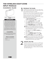 DMP Electronics 1158 Installation guide


