Page is loading ...

CLWI-KPLEX
In-Wall Wireless Lighting Keypad, 230 Vac
Installation Guide
Description
The Crestron
®
CLWI-KPLEX is a companion keypad for CLWI- line of dimmers and
switches. It provides lighting and audio control from multiple locations around the home or
ofce. It is designed to recall scenes, dim loads up and down, and adjust the volume using
the customizable button layout.
The CLWI-KPLEX is shipped with a six-button conguration preinstalled on the keypad.
The button conguration can be replaced with the included large rocker switch or any
combination of up to two adjacent half-size rocker buttons or triple-button pads. All
buttons are congurable for up to three discrete functions via single-press, double-press,
and press-and-hold functionality.
The specications for the CLWI-KPLEX are listed below.
SPECIFICATION DETAILS
Power Requirements 220-240 Vac, 50/60 Hz, line power
Environmental
Temperature
Humidity
0° to 40 °C (32° to 104 °F)
10% to 90% RH (non-condensing)
Enclosure Mountable in a 1-gang UK (BS 4662) electrical box or
1-gang European (DIN 49073) electrical box that is
35 mm (1.38 in) or deeper;
Requires a FP-INTENSE or FP-PURE style faceplate (both
not included)
Dimensions
Height
Width
Depth
72 mm (2.80 in)
72 mm (2.80 in)
32 mm (1.24 in) including front face with buttons
Weight 80 g (3 oz)
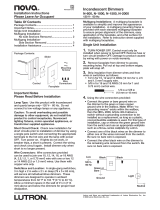
The dimensions of the CLWI-KPLEX are shown below.
72 mm
(2.80 in)
72 mm
(2.80 in)
32 mm
(1.24 in)
51 mm
(2.00 in)
51 mm
(2.00 in)
21 mm
(0.82 in)
Additional Resources
Visit the product page on the Crestron website (www.crestron.com)
for additional information and the latest rmware updates. Use a QR
reader application on your mobile device to scan the QR image.
Installation
To install the CLWI-KPLEX, do the following.
CAUTION: Use on 10 A branch circuits only.
CAUTION: Use 1 x 1.5 - 2.5 mm² wire that complies with BS6004:2000/IEC 60245 and
local electrical codes.
NOTE: Use only copper wire rated for at least 75° C.
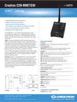
1. Turn the power off at the circuit breaker.
2. Wire the device as shown in the following diagram. Use 1 x 1.5-2.5 mm²
(14-12 AWG) wire. Secure the connections to the CLWI-KPLEX by inserting the wires
into the back of the unit and tightening the screws on the top of the unit with a small
at-head screwdriver.
Neutral
Earth
Live
Line
230 Vac
Tighten the screws
with a small flat-head
screwdriver.
3. Push all power wires back into the electrical box and fasten the device to the
electrical box with the provided screws.
NOTE: Use care when placing the device in the electrical box. Pinched wires
may cause a short circuit.
4. Attach the faceplate (not supplied).
5. Ensure that all buttons, including the program button, actuate without sticking.
6. Restore power at the circuit breaker.
Multigang Installation
In multigang installations, several devices are grouped horizontally or vertically in one
electrical box. When ganging vertically the devices snap together by sliding the bottom of
the upper device into the top of the lower device. This allows the devices to be mounted
closer together.
For a smooth appearance, one-piece multigang faceplates (not included) can be installed.
NOTE: When devices are ganged in a horizontal position, the devices do not interlock.
NOTE: When installing into a multigang box, do not fully tighten devices to box until
the faceplate has been aligned.

Change the Button Assembly
To change or replace the button assembly, follow the procedure below.
1. Squeeze the sides of the button assembly and carefully pull the button assembly off
of the device.
NOTE: When there are two button assemblies installed on a device, press on
one side of the button assembly and carefully remove the button assembly. The
second button assembly can be removed in the manner described above.
2. Insert the new button assemblies onto the device by pressing them into the device.
It might be necessary to squeeze the sides of the button assembly to allow for easier
assembly.
Operation
NOTE: Before using the CLWI-KPLEX, ensure the device is using the latest rmware.
Check for the latest rmware for the CLWI-KPLEX at www.crestron.com/rmware. Load
the rmware onto the device using Crestron Toolbox™ software.
Button Functions
The functionality of the CLWI-KPLEX is based on the control system program.
Device Reboot
To reboot the CLWI-KPLEX, press and hold the setup button for 15 seconds. All LEDs
on the front of the device ash once to indicate that the device is rebooting. Reboot is
completed when the LEDs come back on to normal operating mode.
Wireless Communications
The device connects to the Crestron network via the inNET EX
®
communications
protocol. Use the procedures outlined below to join or leave an inNET EX network and to
verify communications between the device and the control system.
Joining an inNET EX Network
Before a device can be used in a lighting system, it must rst join an inNET EX network
by being acquired by an inNET EX gateway.
NOTE: A device can be acquired by only one gateway.
1. Put the inNET EX gateway into Acquire mode from the unit itself or from Crestron
Toolbox, as described in its manual at www.crestron.com/manuals.
NOTE: In an environment where multiple gateways are installed, only one
gateway should be in Acquire mode at any time.
2. Place the device into Acquire mode.
a. Tap the setup button three times, and then press and hold it down (tap-tap-
tap-press+hold) until all LEDs on the device ash once (this can take up to 10
seconds).
b. Release the button to start the acquire process. The top two LEDs ash slowly to
show that the device is actively scanning the inNET EX network.
• The top two LEDs turn on for 5 seconds to show that the device has been
successfully acquired to the inNET EX network.
• The top LED ashes quickly to indicate that the device was not successfully
acquired by the inNET EX network. Press the setup button to acknowledge
failure to acquire the inNET EX network. Ensure the gateway is in Acquire
mode and within range before attempting the acquire process again.
3. Once all devices have been acquired, take the gateway out of Acquire mode. Refer
to the gateway’s manual for details.
Leaving an inNET EX Network
To leave an inNET EX network:
1. Verify that the device is not within range of an inNET EX gateway that is in Acquire
mode.
2. Tap the setup button three times, and then press and hold it down (tap-tap-tap-
press+hold) until all LEDs on the device ash once (this can take up to 10 seconds),
then release the button. The top two LEDs ash slowly.
3. The top two LEDs then ash quickly to indicate that the device has left the
inNET EX network.
4. Press the setup button to conrm that the device has left the inNET EX network.
Verifying Communications Status
To check the communications status of the device, tap the setup button three times and
then press and hold it down (tap-tap-tap-press+hold) for up to 2 seconds. The top two
LEDs ash to indicate the communications status. Refer to the following table for details.
LEDS COMMUNICATIONS STATUS
Turn on for 5 seconds The device is communicating with the control system.
Flash three times The device is communicating with the gateway, but the
gateway is not communicating with the control system.
Flash twice The device was previously joined to the network but is not
communicating with the gateway.
Flash once The device is not joined to the network.
As of the date of manufacture, the product has been tested and found to comply with specications
for CE marking.
The product warranty can be found at www.crestron.com/warranty.
The specic patents that cover Crestron products are listed at www.crestron.com/legal/patents.
Certain Crestron products contain open source software. For specic information, please visit
www.crestron.com/opensource.
Crestron, the Crestron logo, Crestron Toolbox, and inNET EX are either trademarks or registered
trademarks of Crestron Electronics, Inc. in the United States and/or other countries. Other trademarks,
registered trademarks, and trade names may be used in this document to refer to either the entities
claiming the marks and names or their products. Crestron disclaims any proprietary interest in the
marks and names of others. Crestron is not responsible for errors in typography or photography.
This document was written by the Technical Publications department at Crestron.
©2018 Crestron Electronics, Inc.
Crestron Electronics, Inc. Installation Guide - DOC. 7243B
15 Volvo Drive, Rockleigh, NJ 07647 (2031640)
Tel: 888.CRESTRON 03.18
Fax: 201.767.7576 Specications subject to
www.crestron.com change without notice.
/