Page is loading ...

Crestron Electronics, Inc. Installation Guide - DOC. 7240A
15 Volvo Drive Rockleigh, NJ 07647 (2031637)
Tel: 888.CRESTRON 01.13
Fax: 201.767.7576 Specifications subject to
www.crestron.com change without notice.
Further Inquiries
To locate specific information or resolve questions after reviewing this guide, contact Crestron's True Blue Support at
1-888-CRESTRON [1-888-273-7876] or refer to the listing of Crestron worldwide offices on the Crestron Web site
(www.crestron.com/offices) for assistance within a particular geographic region.
To post a question about Crestron products, log onto the online help section of the Crestron Web site
(www.crestron.com/onlinehelp). First-time users must establish a user account to fully benefit from all available
features.
Future Updates
As Crestron improves functions, adds new features and extends the capabilities of the CLWI-DIMFLVEX, additional
information may be made available as manual updates. These updates are solely electronic and serve as intermediary
supplements prior to the release of a complete technical documentation revision.
Check the Crestron Web site periodically for manual update availability and its relevance. Updates are identified as an
“Addendum” in the Download column.
WARNING: To avoid fire, shock, or death; turn off power at circuit breaker or fuse and test that power is off before
wiring!
NOTES: Observe the following points.
• To be installed and/or used in accordance with appropriate electrical codes and regulations.
• This product should be installed by a qualified electrician
PREPARING AND CONNECTING WIRES
Strip the ends of the wires approximately 6 mm (1/4 in). Use care to avoid nicking the conductors. Twist together
the ends of the wires that share a connection.
Crestron CLWI-DIMFLVEX
In-Wall 0-10 V Dimmer, 230 VAC
Installation Guide
As of the date of manufacture, the CLWI-DIMFLVEX has been tested and found to comply with specifications for CE
marking and standards per EMC and Radiocommunications Compliance Labelling.
Important Notes (Read before wiring and installation.)
CAUTION: TO REDUCE THE RISK OF OVERHEATING AND POSSIBLE DAMAGE TO OTHER
EQUIPMENT, DO NOT INSTALL TO CONTROL A RECEPTACLE OR A TRANSFORMER-SUPPLIED
APPLIANCE.
CAUTION:
• To be installed on 10 A branch circuits only.
• To be installed with 1 x 1.5 - 2.5 mm² wire complying with BS6004:2000/IEC 60245 and local
electrical codes.
• To be used with loads that have a power factor greater than 0.95.
LOW VOLTAGE APPLICATIONS NOTE: Operation of a low voltage circuit with all lamps inoperative or
removed may result in current flow in excess of normal levels. To avoid transformer overheating and
premature transformer failure, Crestron recommends the following:
• Do not operate low voltage circuits without operative lamps in place.
• Replace burned-out lamps as quickly as possible.
• Use transformers that incorporate thermal protection or fuse transformer primary windings to prevent
transformer failure due to overcurrent.
NOTE: The device requires a neutral connection to operate.
• Wiring: Use copper wire only. For supply connections, use wires rated for at least 75° C.
• Lamp Type: For use with permanently installed 0 – 10 V fluorescent, 0 – 10 V LED, any 0 – 10 V
dimmable load.
• Temperature: For use where temperatures are between 0° to 40° C (32° to 104° F).
INTRODUCTION
The CLWI-DIMFLVEX delivers native Crestron
®
control to 0-10 V dimmable fixtures or
switched loads, in new or retrofit 230 volt applications. Featuring reliable infiNET EX
®
wireless technology, the CLWI-DIMFLVEX can be installed in virtually any location thanks to
reliable mesh networking. The CLWI-DIMFLVEX delivers a perfect solution for controlling
newer LED fixtures from a single gang, without requiring external boosters.
Specifications
Specifications for the CLWI-DIMFLVEX are listed in the following table.
CLWI-DIMFLVEX Specifications
Tighten Screws with
Small Flat Head
Screwdriver
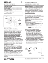
3. When making connections to the device insert the wires into the back of the unit. Use a
small flat head screwdriver to tighten the connection.
Line
230 Vac
Neutral
Neutral
Earth
Live
+
-
0-10 V
Ballast
- + SL
WIRING
The following describes the wiring of a CLWI-DIMFLVEX. Use 1 x 1.5 - 2.5 mm² (14 - 12
AWG) wiring when making connections. Refer to “Installation” on the following page for
installation instructions.
1. Turn power off at the circuit breaker.
2. Wire the device as shown in the following diagram.
4
6
1
3
4
6
Button Functions for CLWI-DIMFLVEX
Rocker with LEDs on Right (Default Layout)
Rocker with LEDs on Left
Rocker with LEDs on Right with Presets
Rocker with LEDs on Left with Presets
Single Right Button Control
1
2
4
5
6
1
2
3
4
6
1
3
1
2
3
4
5
6
2
Single Left Button Control
CONFIGURATION
Before the CLWI-DIMFLVEX can be used in local mode the device must be setup. During the
setup process some or all fixed buttons can be configured for local control. If certain fixed
buttons are to be operated remotely (via control system programming), do not assign local
programming during this process. Buttons programmed for local functionality have
pre-defined functionality which is described in the “Assign Button Functions” section that
follows. Follow the procedures below to setup the device.
Setup Button Configuration
1. Press and hold the setup button (located in the lower right corner of the device) for 5
seconds to enter Button Layout mode. The LEDs that correspond to the current button
layout begin to blink fast. Do not release the setup button.
NOTE: If the setup button is held for 15 seconds without other button presses, the
device restarts. Refer to “Operation - Device Reboot” on the following page for
information.
NOTE: If the setup button is released before all buttons are configured the device
exits Button Layout mode and no changes are saved. The device reverts to its
previously programmed button layout.
2. While holding the setup button and within 5 seconds of the flashing LEDs, press any
button on the device that requires local functionality. Refer to the “Assign Button
Functions” section for valid button layouts. The LED illuminates to verify the button
press.
NOTE: After assigning a button, if no buttons are pressed for 10 seconds the device
exits Button Layout mode without saving the layout. The device reverts to its
previously programmed button layout.
3. Continue holding the setup button and press the remaining buttons on the device that
require local functionality. The LED associated with each button that is selected for
local functionality is illuminated.
NOTE: If an invalid button pattern is selected, the button pattern is not saved.
Setup Minimum and Maximum Dimming Levels
To ensure proper operation of the connected load the minimum and maximum lighting levels
must be established for each device. Follow the procedure below to enter Min/Max Dimming
mode and to make changes to the levels.
1. Press and hold the setup button for 10 seconds until all LEDs light and the middle
LEDs begin blinking. The connected load dims to 50%.
NOTE: During Min/Max Dimming mode the device LEDs blink fast and indicate the
current minimum and maximum dimming levels.
NOTE: The maximum level is saved only if the light level is raised above 75% (either
of the top two LEDs is illuminated).
NOTE: The minimum level is saved only if the light level is lowered below 45%
(either of the bottom two LEDs is illuminated).
2. Using any available top button on the dimmer, raise the load to the maximum desired
level. If the connected load begins to cycle or flash, the level must be reduced.
3. Save the maximum dim level by holding the setup button for 2 seconds.
4. Using any available bottom button on the dimmer, lower the load to the minimum
desired level. If the connected load begins to flicker, the level must be increased.
5. Save the minimum dimming level by holding the setup button for 2 seconds.
6. Tap the setup button to exit Min/Max Dimming mode.
Setting Preset Levels
The device can recall and store up to three presets depending on the installed button
configuration and local programming. Refer to the “Operation” section for configurations that
utilize presets. To set the presets, follow the procedure below:
1. Adjust the light level to the desired level.
2. Enter Programming mode by tapping the setup button. Buttons capable of storing
presets flash the LED.
3. Press and hold the desired preset button until the LED blinks (about 2 seconds).
If a button is not pressed, the device exits Programming mode after about 5 seconds.
ASSIGN BUTTON FUNCTIONS
Default Button Functions
The CLWI-DIMFLVEX uses a fixed button configuration that fuctions differently depending on
the button assembly that is installed. Refer to “Change Button Assemblies” section for
instructions on how to change the button assembly. The illustrations in the following column
show the available button assembly configurations that are available for the device. The
button number with a circle around it identifies the button(s) configured for local operation
during this procedure. All other fixed buttons shown (without a circle) are configured through
remote control system programming.

Physical Description
This section provides information on the connections, controls and indicators available on the
CLWI-DIMFLVEX.
CLWI-DIMFLVEX Dimensions
72 mm
(2.80 in)
72 mm
(2.80 in)
32 mm
(1.24 in)
51 mm
(2.00 in
51 mm
(2.00 in
+
-
21 mm
(0.82 in)
Return and Warranty Policies
Merchandise Returns / Repair Service
1. No merchandise may be returned for credit, exchange or service without prior authorization
from Crestron. To obtain warranty service for Crestron products, contact an authorized
Crestron dealer. Only authorized Crestron dealers may contact the factory and request an
RMA (Return Merchandise Authorization) number. Enclose a note specifying the nature of
the problem, name and phone number of contact person, RMA number and return
address.
2. Products may be returned for credit, exchange or service with a Crestron Return
Merchandise Authorization (RMA) number. Authorized returns must be shipped freight
prepaid to Crestron, 6 Volvo Drive, Rockleigh, N.J. or its authorized subsidiaries, with RMA
number clearly marked on the outside of all cartons. Shipments arriving freight collect or
without an RMA number shall be subject to refusal. Crestron reserves the right in its sole
and absolute discretion to charge a 15% restocking fee plus shipping costs on any
products returned with an RMA.
3. Return freight charges following repair of items under warranty shall be paid by Crestron,
shipping by standard ground carrier. In the event repairs are found to be non-warranty,
return freight costs shall be paid by the purchaser.
Crestron Limited Warranty
Crestron Electronics, Inc. warrants its products to be free from manufacturing defects in materials
and workmanship under normal use for a period of three (3) years from the date of purchase from
Crestron, with the following exceptions: disk drives and any other moving or rotating mechanical
parts, pan/tilt heads and power supplies are covered for a period of one (1) year; touch screen
display and overlay components are covered for 90 days; batteries and incandescent lamps are
not covered.
This warranty extends to products purchased directly from Crestron or an authorized Crestron
dealer. Purchasers should inquire of the dealer regarding the nature and extent of the dealer's
warranty, if any.
Crestron shall not be liable to honor the terms of this warranty if the product has been used in any
application other than that for which it was intended or if it has been subjected to misuse,
accidental damage, modification or improper installation procedures. Furthermore, this warranty
does not cover any product that has had the serial number altered, defaced or removed.
This warranty shall be the sole and exclusive remedy to the original purchaser. In no event shall
Crestron be liable for incidental or consequential damages of any kind (property or economic
damages inclusive) arising from the sale or use of this equipment. Crestron is not liable for any
claim made by a third party or made by the purchaser for a third party.
Crestron shall, at its option, repair or replace any product found defective, without charge for parts
or labor. Repaired or replaced equipment and parts supplied under this warranty shall be covered
only by the unexpired portion of the warranty.
Except as expressly set forth in this warranty, Crestron makes no other warranties, expressed or
implied, nor authorizes any other party to offer any warranty, including any implied warranties of
merchantability or fitness for a particular purpose. Any implied warranties that may be imposed by
law are limited to the terms of this limited warranty. This warranty statement supersedes all
previous warranties.
3. Insert the new button assemblies onto the device by pressing them into the device. It
might be necessary to squeeze the sides of the button assembly to allow for easier
assembly.
Install Button Assembly
CHANGE BUTTON ASSEMBLIES
Follow the procedure below if the button assemblies need to be changed or replaced.
1. Remove the button assembly by squeezing the sides of the button assembly near the
center of the device.
2. Remove the button assembly by carefully pulling the button assembly off of the device.
Refer to the illustrations that follow.
NOTE: When there are two or more button assemblies installed on a device, press
on one side of the button assembly and carefully remove the button assembly. The
second button assembly can be removed in the manner described in step 1 and 2
above. Refer to the illustrations that follow.
Remove Button Assembly
INSTALLATION
Single Gang Installation
Refer to the following procedure and illustration to install the device into a single gang
electrical box. Electrical box depth must be 35 mm (1.38 in) or deeper.
1. Push all power wires back into the electrical box and fasten the device to the electrical
box with the provided screws. Refer to the following illustration for details.
NOTE: Use care when placing the device in the electrical box. Pinched wires may
cause a short circuit.
2. Attach the faceplate (not supplied).
3. Ensure all buttons, including the program button, actuate without sticking.
4. Restore power at the circuit breaker.
Multigang Installation
In multigang installations, several devices are grouped horizontally or vertically in one
electrical box. When ganging vertically the devices snap together by sliding the bottom of the
upper device into the top of the lower device. This allows the devices to be mounted closer
together.
For a smooth appearance, one-piece multigang faceplates (not supplied) can be installed.
NOTE: When devices are ganged in a horizontal position, the devices do not interlock.
NOTE: When installing into a multigang box, do not fully tighten devices to box until
faceplate has been aligned.
WIRELESS COMMUNICATIONS
The device connects to the Crestron network via the infiNET EX communications protocol.
Use the procedures outlined below to join or leave an infiNET EX network and to verify
communications between the device and the control system.
Joining an infiNET EX Network
Before a device can be used in a lighting system, it must first join an infiNET EX network by
being acquired by an infiNET EX gateway.
NOTE: A device can be acquired by only one gateway.
1. Put the infiNET EX gateway into Acquire mode from the unit itself or from Crestron
Toolbox, as described in the latest version of its manual, which is available from the
Crestron Web site (www.crestron.com/manuals).
NOTE: In an environment where multiple gateways are installed, only one gateway
should be in Acquire mode at any time.
2. Place the device into Acquire mode by doing the following:
a. Tap the setup button three times then press and hold it down (tap-tap-tap-
press+hold) until all LEDs on the device flash once (this can take up to 10 seconds).
b. Release the button to start the acquire process. The top two LEDs blink slowly to
show that the device is actively scanning the infiNET EX network.
• The top two LEDs turn on for 5 seconds to show that the device has been
successfully acquired to the infiNET EX network.
• The top two LEDs blink fast to indicate that the device was not successfully
acquired to the infiNET EX network. Tap the setup button to acknowledge failure
to acquire to the infiNET EX network. Ensure gateway is in acquire mode and
within range before attempting the acquire process again.
Leaving an infiNET EX Network
To leave an infiNET EX network put the device into Acquire mode, as described in “Joining
an infiNET EX Network” above, when no gateway is in Acquire mode.
Verifying Communications Status
To check the communication status of the device tap the setup button three times then press
and hold it down (tap-tap-tap-press+hold) for 2 seconds. The top two LEDs blink to indicate
the communication status. Refer to the following table for details.
OPERATION
Upgrade Firmware
The device receives firmware upgrades via infiNET EX over-the-air firmware upgrades. Refer
to the Crestron Toolbox™ help file for details.
Restore Default Settings
If needed, use the following command to reset the device to its factory default settings. Send
the console command “restore” to perform a restore of the factory defaults. All local
programming needs to be reset.
Device Reboot
To reboot the CLWI-DIMFLVEX press and hold the setup button for 15 seconds. Release the
setup button after all LEDs on the front of the device flash to full on and then turn off. This
indicates that the device is rebooting. Reboot is completed once the LEDs come back on to
normal operating mode.
The specific patents that cover Crestron products are listed at patents.crestron.com.
Crestron, the Crestron logo, Crestron Toolbox and infiNET EX are either trademarks or registered
trademarks of Crestron Electronics, Inc. in the United States and/or other countries. Other trademarks,
registered trademarks and trade names may be used in this document to refer to either the entities
claiming the marks and names or their products. Crestron disclaims any proprietary interest in the marks
and names of others.
©2013 Crestron Electronics, Inc.
/