Page is loading ...

1
Multigang Installations: A multigang faceplate is
available to simplify and improve the appearance
of your installation. A multigang mounting frame is
provided with each standard multigang faceplate
to ensure proper alignment of the dimmers, easy
application of the faceplate, and a fl at surface for
the installation. Refer to instruction sheet supplied
with multigang faceplates.
Single Unit Installation
1. TURN POWER OFF. Control must only be
installed when power is turned OFF. Remove fuse or
turn circuit breaker OFF. Damage to product caused
by wiring with power on voids warranty.
2. Remove faceplate from dimmer to access
mounting holes. Pull out at top and bottom edges,
plate will snap off.
3. Strip insulation from dimmer wires and from
wires in switchbox as follows:
• 1/2 in for 10, 12 and 14 AWG (12 mm for 4, 2.5
and 1.5 mm
2
) supply wire.
• 5/8 in for 16 and 18 AWG (15 mm for 1 and
0.75 mm
2
) control wire.
4. Using the wire connectors provided:
• Connect the green or bare ground wire on
the dimmer to the green or bare copper
ground wire in the wallbox. Note: When “no
grounding means” exists within the wallbox,
then the NEC
®
2008, Article 404.9 allows a
switch without a grounding connection to be
installed as a replacement, as long as a plastic,
noncombustible wallplate is used. For this type of
installation, cap or remove the green ground wire
from the switch and use an appropriate wallplate
such as a Nova
®
series wallplate by Lutron.
• Connect one of the black wires on the dimmer to
either one of the wires removed from the switch.
Be sure no bare wire is exposed.
• Connect the other black wire on the dimmer to
the remaining wire removed from the switch. Be
sure no bare wire is exposed.
Lutron and Nova are registered trademarks of Lutron Electronics Co., Inc.
© 2008 Lutron Electronics Co., Inc.
Table Of Contents
Package Contents ................................................. 1
Important Notes ..................................................... 1
Single Unit Installation .......................................... 1
Multigang Installation-
No side Sections Removed ............................ 2
Multigang Installation-
Side Section Removed ................................... 3
Installation Assistance .......................................... 4
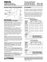
Package Contents:
Important Notes
Please Read Before Installation
Lamp Type: Use this product with incandescent
and quartz lamps only--120 V~ 60 Hz. Do not
connect to low-voltage lamps or any appliance.
Caution: To avoid overheating and possible
damage to other equipment, do not install this
product to control receptacles, fl uorescent
lighting fi xtures, motor-operated appliances, or
transformer supplied appliances.
Short Circuit Check: Check new installation for
short circuits prior to installation of dimmer by using
a single pole switch and connecting the appropriate
terminals to the hot wire and the lamp with power
OFF. Turn power on. If lights do not work, or
breaker trips, a short is present. Correct the wiring
and check circuit again. Install dimmer only when
short is no longer present.
Wire Connectors: Wire connectors provided
can be used to join one 10, 12, 14, 16, or 18 AWG
(4, 2.5, 1.5, 1, or 0.75 mm
2
) wire with one or two 12
or 14 AWG (2.5 or 1.5 mm
2
) wires. Use them with
copper wire only.
Switchbox and Location: A single-gang switchbox,
3 in high x 2 in wide x 2
1
⁄2 in deep (76 x 5 x 63 mm),
will service all individual Nova dimmers. These
dimmers are designed to operate in ambient
temperatures from 32 °F to 104 °F (0 °C to 40 °C).
Allow a minimum space in the wall of 4
1
/2 in (114
mm) above and below the dimmers for proper heat
dissipation.
1/2 in or 5/8 in
(12 mm or 15 mm)
Slider
Control
Faceplate
Wire
Connectors
Mounting
Screws
120 V~
60 Hz
Black
Black
Neutral
Light
Live
Green or
Bare
Ground
120 V~
60 Hz
Installation Instructions
Please Leave for Occupant
Incandescent Dimmers
N-600, N-1000, N-1500, N-2000
120 V~ 60 Hz
P/N 030-1013

2
1. Determine the number of switchboxes necessary
by using the Switchbox Requirement Chart (Table A).
When ganging any combination of small dimmers
(N-600, N-1000) and large dimmers (N-1500, N-2000),
keep all small dimmerstogether at one end of the
gang and all large dimmers together at the other end
of the gang.
2. When ganging an even number of small
controls use gangable switchboxes with tapped
ears. Do not use plaster rings or gangbox covers.
One switchbox in addition to the total number of
controls is required in order to provide space for
faceplates (e.g. 4 dimmers require 5 switchboxes).
Place additional switchboxes 3/4 in (19 mm) apart
from other switchbox(es) to provide space for
faceplate(s).
Multigang Installation-
No Side Sections Removed (No Derating Required)
In multigang installations, several dimmers or controls
are grouped horizontally in one ganging switchbox
or in a series of connected switchboxes. Multigang
faceplates are available to simplify and improve the
appearance of this installation. A multigang mounting
frame is provided with standard multigang faceplates
which ensures proper alignment of dimmers, easy
application of the faceplate, and a fl at surface for the
installation. Refer to instruction sheet (supplied with
multigang faceplate) when using these components.
Installation of dimmers without removing side
sections allows operation at full capacity (no
derating). Follow instructions below. For retrofi t
installations side sections can be removed to fi t
existing switchboxes. This requires derating and is
described in "Multigang Installation - Side Sections
Removed" on page 3.
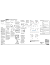
5. Push wires into switchbox, allowing room for
dimmer backbox to be inserted.
6. Mount dimmer to switchbox using the 2 provided
screws in the center mounting holes (offset
mounting holes are for multigang installation).
Unit must be mounted vertically.
Table A. Switchbox Requirement Chart
No Side Sections Removed
*See item #2
Single-gang
Wallbox
3/4 in (19 mm) space (use
chase nipple or Lutron P/N
“PLUS-ADPTR-3.5”)
Four-gang
wallbox
Ground
(Green or Bare)
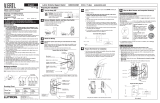
7. Snap faceplate on dimmer.
8. Turn power ON. Push slider up to increase light
and down to decrease light. Full "down" position
will turn light off.
Offset Mounting Holes
Center Mounting Holes
Press plate Until Tabs Snap In
Faceplate
Tab s
Number of Small Controls
0 1 2 3 4 5 6
Number of Switchboxes Required
0 0 1 1+1* 4 4+1* 7 7+1*
Number 1 1 3 5 6 8 9 11
of Large 2 4 6 7 9 10 12 13
Controls 3 6 8 10 11 13 14 16
4 9 11 12 14 15 17 18

3
3. Turn power OFF. Wire each dimmer according
to steps 3 and 4 in "Single Unit Installation".
4. Install controls in switchbox(es). Use center
mounting holes for fi rst unit, then use offset mounting
holes as required for proper alignment. Allow 1/32
in (.79 mm) between controls for ease in attaching
faceplates.
5. Just snap on multigang faceplate (or multiple
single faceplates) and adjust up or down for snug
fi t. Multigang faceplates (with mounting frames and
instructions) are available in a variety of colors and
sizes to simplify and beautify your installation.
Multigang Installation--
Side Sections Removed (Derating Required)
In multigang installations several dimmers or controls
are grouped horizontally in one ganging switchbox
or in a series of connected switchboxes. Multigang
faceplates are available to simplify and improve the
appearance of this installation. A multigang mounting
frame is provided with standard multigang faceplates
which ensures proper alignment of dimmers, easy
application of the faceplate, and a fl at surface for the
installation. Refer to instruction sheet (supplied with
multigang faceplate) when using these components.
1. Derating is necessary when side sections are
removed. Use Derating Chart (Table B) to determine
maximum wattage of lamps safely dimmed when
side sections are removed. Match the dimmer model
number and the number of side sections removed to
determine the maximum load that can be controlled.
Table B. Derating Chart - Maximum Wattage
Control No Sides 1 Side 2 Sides
Model Size Removed Removed Removed
N-600 S 600 W 600 W 500 W
N-1000 S 1000 W 900 W 700 W
N-1500 L 1500 W 1250 W 1000 W
N-2000 L 2000 W 1800 W 1500 W
2. Determine the number of switchboxes necessary
by using the Switchbox Requirement Chart (Table C).
When ganging any combination of small dimmers
(N-600, N-1000) and large dimmers (N-1500, N-2000),
place all small dimmers together at one end of the
gang and all large dimmers at the other end of the
gang.
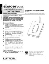
3. Remove only inner side sections. Using pliers,
bend side sections as far as you can and then back
to their original positions. Repeat several times
until side sections break off.
Note: Do not remove outer side sections of the two
dimmers which are on the ends of the gang.
4. Turn power OFF. Wire each dimmer according
to steps 3 and 4 in "Single Unit Installation".
Grounds need to be common.
5. Install controls in switchbox(es). Use center
mounting holes. (With large controls, you can
use offset mounting holes as required for proper
alignment). Allow 1/32 in (.79 mm) between controls
for ease in attaching faceplates.
6. Just snap on a multigang faceplate or multiple
single faceplates (see "Faceplate Cutting" on next
page) and adjust up or down for snug fi t. Multigang
faceplates (with mounting frames and instructions)
are available in a variety of colors and sizes to
simplify and beautify your installation.
Table C. Switchbox Requirement Chart
Side Sections Removed
Side section break-off points
Offset Mounting Holes
Center Mounting Holes
Number of Small Controls
0 1 2 3 4 5 6
Number of Switchboxes Required
0 0 1 2 3 4 5 6
Number 1 1 3 4 5 6 7 8
of Large 2 3 5 6 7 8 9 10
Controls 3 5 7 8 9 10 11 12
4 7 9 10 11 12 13 14

4
Lutron Electronics Co., Inc.
7200 Suter Road
Coopersburg, PA 18036-1299
Made and printed in U.S.A. 8/08 P/N 030-1013 Rev. A
Faceplate Cutting
Some faceplates will need to be cut if removing
side sections of dimmers and not using a multigang
faceplate. Position faceplate on a soft cloth face
down. Press fi rmly and score the groove on the
back of faceplate with a razor-sharp knife, using
vertical side groove to keep knife on straight
course. Bend section back and forth to break it off.
Smooth edges by placing fi ne-grained sandpaper
on a fl at surface and rub edge of the faceplate over
the sandpaper a few times. Hold faceplate steady
as you rub to keep a true edge.
Multigang faceplates, which eliminate the need to
cut individual faceplates, are available from Lutron
in a variety of colors to simplify and beautify your
installation.
Worldwide Technical and Sales
Assistance
If you have questions concerning the installation or
operation of this product, call the Lutron Technical
Support Center. Please provide exact model
number when calling.
1.800.523.9466 (U.S.A., Canada, and the Caribbean)
Other countries call +1.610.282.3800
Fax +1.610.282.6311
Visit our web site at www.lutron.com
LIMITED WARRANTY
(Valid only in U.S.A., Canada, Puerto Rico, and the Caribbean.)
Lutron will, at its option, repair or replace any unit that is defective in materials or manufacture
within one year after purchase. For warranty service, return unit to place of purchase or
mail to Lutron at 7200 Suter Rd., Coopersburg, PA 18036-1299, postage pre-paid.
THIS WARRANTY IS IN LIEU OF ALL OTHER EXPRESS WARRANTIES, AND THE IMPLIED
WARRANTY OF MERCHANTABILITY IS LIMITED TO ONE YEAR FROM PURCHASE.
THIS WARRANTY DOES NOT COVER THE COST OF INSTALLATION, REMOVAL OR
REINSTALLATION, OR DAMAGE RESULTING FROM MISUSE, ABUSE, OR DAMAGE
FROM IMPROPER WIRING OR INSTALLATION. THIS WARRANTY DOES NOT COVER
INCIDENTAL OR CONSEQUENTIAL DAMAGES. LUTRON'S LIABILITY ON ANY CLAIM
FOR DAMAGES ARISING OUT OF OR IN CONNECTION WITH THE MANUFACTURE,
SALE, INSTALLATION, DELIVERY, OR USE OF THE UNIT SHALL NEVER EXCEED THE
PURCHASE PRICE OF THE UNIT.
This warranty gives you specifi c legal rights, and you may have other rights which vary
from state to state. Some states do not allow limitations on how long an implied warranty
lasts, so the above limitation may not apply to you. Some states do not allow the exclusion
or limitation of incidental or consequential damages, so the above limitation or exclusion
may not apply to you.
/