Crestron DIN-AP3MEX User guide

Category
Networking
Type
User guide

Crestron DIN-AP3MEX is a 3-Series Control System automation processor with built-in infiNET EX® and ER wireless gateway, high-speed Ethernet, Cresnet® network support, and BACnet network/IP support, allowing for versatile automation system configurations using Crestron and third-party DIN rail-mountable devices.

Crestron DIN-AP3MEX is a 3-Series Control System automation processor with built-in infiNET EX® and ER wireless gateway, high-speed Ethernet, Cresnet® network support, and BACnet network/IP support, allowing for versatile automation system configurations using Crestron and third-party DIN rail-mountable devices.

DIN-AP3MEX
DIN Rail 3-Series
®
Automation Processor with inNET EX
®
& ER Wireless Gateway
Installation & Operation Guide
Hardware Hookup
Make any necessary connections to the device, and apply power after all connections
have been made.
NOTE: When making connections to the DIN-AP3MEX, observe the following points:
Use Crestron power supplies for Crestron equipment.
The included cable cannot be extended.
Hardware Connections for the DIN-AP3MEX (Front View)
Congure the Control System
The control system can be congured using Crestron Toolbox or the built-in, web-based
setup tool.
Crestron Toolbox
Use Crestron Toolbox to establish communication with and to congure the control
system. For details, refer to the embedded Crestron Toolbox help le.
Web-Based Setup Tool
1. Use Crestron Toolbox to set the time and the time zone. For details, refer to the
embedded Crestron Toolbox help le.
2. Open the Internet Explorer
®
web browser and enter the IP address of the
DIN-AP3MEX. The control system’s splash page is displayed.
NOTE: The web-based setup tool is accessible only from Internet Explorer.
NOTE: If a security warning is displayed, click Install to continue.
DIN-AP3MEX Splash Page
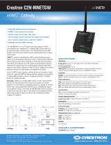
Description
The DIN-AP3MEX is a Crestron
®
3-Series Control System
®
automation processor that is
designed for DIN rail-mounting applications. The device includes a built-in inNET EX
®
and ER wireless gateway, high-speed Ethernet, Cresnet
®
network support, and BACnet
network/IP support. DIN rail mounting allows for conguring complete automation
systems using the DIN-AP3MEX along with additional Crestron and third-party DIN
rail-mountable devices.
Installation
CAUTION: This equipment is intended for indoor use only. Mount the DIN-AP3MEX in
a well-ventilated area. The ambient temperature must be 0 ˚C to 40 ˚C (32 ˚F to 104 ˚F).
The relative humidity must be 10% to 90% (noncondensing).
CAUTION: To prevent overheating, do not operate the DIN-AP3MEX in an area that
exceeds the environmental temperature range listed above. Consider using forced air
ventilation to reduce overheating. Also use caution if installing the control system in a
closed or multiunit rack assembly, since the operating ambient temperate of the
environment may be greater than the room ambient temperature. Contact with thermal
insulating materials on all sides of the unit should be avoided.
NOTES: Observe the following guidelines:
Install and use the DIN-AP3MEX in accordance with appropriate electrical codes
and regulations.
A licensed electrician must install the DIN-AP3MEX.
When installing in an enclosure, group high-voltage devices separately from
low-voltage devices.
NOTE: Before using the DIN-AP3MEX, ensure that the device is using the latest
rmware. Check for the latest rmware for the DIN-AP3MEX at
www.crestron.com/rmware. Load the rmware onto the device using
Crestron Toolbox™ software.
Preparing and Connecting Wires
When making connections, strip the ends of the wires approximately 7/16 in (11 mm).
Use care to avoid nicking the conductors. Tighten the connector to 5 in-lb
(0.5 to 0.6 Nm). The wire gauge should be 14 to 26 AWG.
Installing the DIN-AP3MEX
Use the DIN-AP3MEX in a well-ventilated area. The venting holes should not be
obstructed under any circumstances. The DIN-AP3MEX is designed for installation in a
DIN rail. Refer to the following diagram when installing.
Installing the DIN-AP3MEX
Additional Resources
Visit the product page on the Crestron website (www.crestron.com)
for additional information and the latest rmware updates. Use a QR
reader application on your mobile device to scan the QR image.
Hardware Connections for DIN-AP3MEX (Bottom View)
NOTE: Ensure that the unit is properly grounded by connecting the chassis ground lug
to an earth ground (building steel).
NOTE: To prevent overheating, do not operate this product in an area that exceeds
the environmental range stated in the “Installation” section.
3. Click Setup to display the DIN-AP3MEX setup menu. The DIN-AP3MEX Setup
menu displays the IP address, hostname, and MAC address of the device. The
screen also allows access to various setup and programming screens.
Use the following procedure to install the DIN-AP3MEX:
1. Use a at object (such as a at-head screwdriver) to pull the DIN rail release tab
downward.
2. Place the top of the DIN-AP3MEX’s rail mount over the top of the DIN rail.
3. Tilt the bottom of the DIN-AP3MEX toward the DIN rail until it snaps into place.
NOTE: When mounting DIN rail products, use a at-head screwdriver to pull the
DIN rail release tab while snapping the device onto the DIN rail.
To remove the DIN-AP3MEX from the DIN rail, use a small, at object (such as a at-head
screwdriver) to pull the DIN rail release, and then tilt the bottom of the DIN-AP3MEX
away from the DIN rail.
NOTE: Certain third-party DIN cabinets provide space for an informational label
between each DIN rail row. Crestron’s Engraver software (version 4.0 or later) can
generate appropriate labels for all Crestron DIN rail products.
Mounting the Antenna
It is advised that the DIN-AP3MEX’s antenna should be located outside of the DIN
cabinet (or similar mounting enclosure). Use the Crestron ANT-EXT-10 (sold separately) to
mount the antenna outside of the enclosure:
1. Remove the protective dust cover from the connector at the top of the
ANT-EXT-10.
2. Attach the connector at the end of the ANT-EXT-10’s attached cable to the
DIN-AP3MEX’s antenna connector.
3. Attach the DIN-AP3MEX’s antenna to the connector at the top of the ANT-EXT-10,
and then mount the ANT-EXT-10 in an appropriate location outside of the
enclosure.
NOTE: For antenna placement and orientation guidelines, refer to the
Best Practices for Installation and Setup of Crestron RF Products (Doc. 6689) at
www.crestron.com/manuals.
4. From the DIN-AP3MEX’s Setup menu, click the following options to congure the
control system:
Ethernet Setup congures the DIN-AP3MEX’s Ethernet settings and displays
DHCP, hostname, IP address, subnet mask, default router, domain, and MAC
address settings. In the Ethernet Setup menu, there are additional options:
• Click Advanced Settings to specify DNS servers, web server settings, and
SSL settings.
• Click MyCrestron Dynamic DNS to configure the myCrestron.com Dynamic
DNS service.
• Click Ethernet Diagnostics to test the Ethernet communications.
• Click Reboot to reboot the DIN-AP3MEX.
Application Setup selects the programs to be loaded on start-up and the
controls that programs are running.
Diagnostics displays information about the connected devices, hardware
conguration, and error logs.
About displays rmware information.
Click the back button ( ) to return to the previous screen.
Assign the RF Channel
Set the RF channel of the DIN-AP3MEX prior to operation. The DIN-AP3MEX can operate
on channels 11 through 26. Crestron recommends using RF channel 15 or 20. The
default RF channel is 15.
For optimum performance when installing a DIN-AP3MEX in a Wi-Fi
®
network
environment, do not set the RF channel within a Wi-Fi channel band. Refer to the
information below when choosing the RF channel in a Wi-Fi environment:
Gateway channels 11 through 14 are within the Wi-Fi channel 1 band.
Gateway channel 15 is adjacent to Wi-Fi channels 1 and 6.
Gateway channels 16 through 19 are within the Wi-Fi channel 6 band.
Gateway channel 20 is adjacent to Wi-Fi channels 6 and 11.
Gateway channels 21 through 24 are within the Wi-Fi channel 11 band.
Gateway channel 25 is adjacent to Wi-Fi channel 11.
Gateway channel 26 is neither within nor adjacent to any Wi-Fi band.
NOTE: Crestron’s RF devices are divided into two categories: inNET EX devices and
Crestron Extended Range (ER) devices. inNET EX devices automatically set their RF
channel assignment to match the gateway’s channel, whereas ER devices must have
their RF channel manually assigned to match the gateway’s channel.
Use Crestron Toolbox software to set the DIN-AP3MEX’s RF channel. From the
“System Info” window, select Functions > inNET EX Gateway from the menu bar.
Refer to the Crestron Toolbox software help le for details.
LAN:
10 Base-T / 100 Base-TX
Ethernet to LAN
Hardware Connections for DIN-AP3MEX (Top View)
NET (24 Y Z G):
To any Cresnet
®
network device
COMPUTER:
To computer
console
MEMORY:
For SD card
DIN rail
release tab
DIN rail
(not included)
DIN-AP3MEX
Rail mount
(top)
DIN-AP3MEX Setup Menu
Ground
Antenna:
To included antenna
or antenna extender
Acquire Devices to the Control System
Crestron inNET EX and ER devices can communicate with a DIN-AP3MEX after they
have been acquired by the control system’s gateway. A device can be acquired to only
one gateway. Acquire mode can be activated by using Crestron Toolbox or by pushing
the ACQUIRE button on the control system’s front panel.
NOTE: Use Crestron Toolbox to set the RF channel before starting the acquiring
process. The default RF channel is 15. ER devices must be congured to match the
channel setting on the gateway.
NOTE: Acquire mode can be activated approximately 15 seconds after power is
applied to the DIN-AP3MEX.
NOTE: The DIN-AP3MEX must be placed in Acquire mode before an inNET EX
device is placed into Acquire mode.
To acquire an inNET EX or ER device via the ACQUIRE button on the DIN-AP3MEX,
use the following procedure:
1. Press ACQUIRE on the DIN-AP3MEX to enter Acquire mode. The Acquire LED
lights to indicate that the unit is ready to acquire inNET EX and ER devices.
NOTE: Acquire mode automatically deactivates after one hour. The timeout
period can be changed from Crestron Toolbox.
2. Bring the inNET EX or ER device within range of the gateway, and then place it in
Acquire mode as described in its manual. Once the device enters Acquire mode, it
will be acquired within two minutes.
3. Repeat step 2 for each inNET EX or ER device that needs to be acquired.
4. Press ACQUIRE on the DIN-AP3MEX to exit Acquire mode. The Acquire LED turns
off.
Troubleshooting
The following table provides corrective action for possible troubleshooting situations. If
further assistance is required, please contact a Crestron customer service representative.
DIN-AP3MEX Troubleshooting Table
TROUBLE POSSIBLE CAUSE(S) CORRECTIVE ACTION
The device does not
function.
The d
evice is not
communicating with the
network.
The device is not receiving
power from a Crestron
power supply.
The device is not receiving
sufcient power.
Use the provided
Crestron power supply.
Verify that the
connections are correct
and secure.
The MSG LED illuminates.
Use the Cresnet Power
Calculator to help
calculate how much
power is needed.
There is a hardware or
software failure.
A poor analog versus The compilation error
RLCMCVT166 or
RLCMCVT177 appears.
Verify that the hardware
conguration matches
the software
conguration. Use
Crestron Toolbox
to display the error log.
serial signal denition
exists in the SIMPL
Windows program.
The s
ystem locks up.
Conrm that the signal
denition is properly
dened in the program.
There are various causes.
A Cresnet device does not
respond.
The device is not wired
correctly.
Verify that the Cresnet
wiring is correct and
secure.
used.
An improper NET IP was
Hold down the SW-R
button on the control
system front panel to
bypass the program and
to communicate directly
with the processor. Refer
to "Troubleshooting
Communications" in the
Crestron 3-Series
Control System
Reference Guide
(Doc. 7150) at
www.crestron.com/
manuals for more details.
Verify that the device ID
matches the NET ID in
the program.
The device is improperly
grounded.
There is a loss of
functionality due to
electrostatic charge.
Check that all ground
connections have been
properly made.
DIN-AP3MEX Troubleshooting Table (continued)
TROUBLE POSSIBLE CAUSE(S) CORRECTIVE ACTION
The A/V system device
does not respond.
The IRP2 or the serial port
is not placed properly.
The wrong IR/serial port
was used.
Verify the placement of
the IRP2 (hold the
phosphor card under the
IRP2 while pressing the
button), and tighten
serial cables.
Verify that the proper
IR/serial port is dened.
The serial cable is not wired
correctly.
The device is not receiving
Verify that serial cable is
wired correctly for
RS-232, -422, and -485.
sufcient power.
Use the Cresnet Power
Calculator to help
calculate how much
power is needed.
Use Crestron Toolbox to
poll the network. Verify
that the network is
connected to the device.
As of the date of manufacture, the product has been tested and found to comply with specications
for CE marking.
This product is Listed to applicable UL
®
Standards and requirements tested by Underwriters
Laboratories Inc.
Ce produit est homologué selon les normes et les exigences UL applicables par Underwriters
Laboratories Inc.
Federal Communications Commission (FCC) Compliance Statement
This device complies with part 15 of the FCC Rules. Operation is subject to the following conditions:(1)
This device may not cause harmful interference and (2) this device must accept any interference
received, including interference that may cause undesired operation.
CAUTION: Changes or modications not expressly approved by the manufacturer responsible for
compliance could void the user’s authority to operate the equipment.
NOTE: This equipment has been tested and found to comply with the limits for a Class B digital
device, pursuant to part 15 of the FCC Rules. These limits are designed to provide reasonable
protection against harmful interference in a residential installation. This equipment generates, uses and
can radiate radio frequency energy and, if not installed and used in accordance with the instructions,
may cause harmful interference to radio communications. However, there is no guarantee that
interference will not occur in a particular installation. If this equipment does cause harmful interference
to radio or television reception, which can be determined by turning the equipment off and on, the
user is encouraged to try to correct the interference by one or more of the following measures:
Reorient or relocate the receiving antenna.
Increase the separation between the equipment and receiver.
Connect the equipment into an outlet on a circuit different from that to which the receiver is
connected.
Consult the dealer or an experienced radio/TV technician for help.
Industry Canada (IC) Compliance Statement
CAN ICES-3(B)/NMB-3(B)
Crestron software, including without limitation, product development software and product operating
system software is licensed to Crestron dealers and Crestron Service Providers (CSPs) under a limited
non-exclusive, non-transferable license pursuant to a separate end-user license agreement. The terms
of this end user license agreement can be found on the Crestron website at
www.crestron.com/legal/software_license_agreement.
The product warranty can be found at www.crestron.com/warranty.
The specic patents that cover Crestron products are listed at patents.crestron.com.
Certain Crestron products contain open source software. For specic information, please visit
www.crestron.com/opensource.
Crestron, the Crestron logo, 3-Series, 3-Series Control System, Cresnet, Crestron Toolbox,
inNET EX, and the inNET EX logo are either trademarks or registered trademarks of Crestron
Electronics, Inc. in the United States and/or other countries. Internet Explorer is either a trademark or a
registered trademark ofMicrosoft Corporation in the United States and/or other countries. UL and the
UL logo are either trademarks or registered trademarks of Underwriters Laboratories, Inc. in the United
States and/or other countries. Wi-Fi is either a trademark or a registered trademark of the Wi-Fi
Alliance in the United States and/or other countries.
Other trademarks, registered trademarks, and trade names may be used in this document to refer to
either the entities claiming the marks and names or their products. Crestron disclaims any proprietary
interest in the marks and names of others. Crestron is not responsible for errors in typography or
photography.
This document was written by the Technical Publications department at Crestron.
©2016 Crestron Electronics, Inc.
Crestron Electronics, Inc. Installation & Operation Guide - DOC. 7492C
15 Volvo Drive Rockleigh, NJ 07647 (2035918)
Tel: 888.CRESTRON 12.16
Fax: 201.767.7576 Specications subject to
www.crestron.com change without notice.
  • Page 1 1
  • Page 2 2

Crestron DIN-AP3MEX User guide

Category
Networking
Type
User guide

Crestron DIN-AP3MEX is a 3-Series Control System automation processor with built-in infiNET EX® and ER wireless gateway, high-speed Ethernet, Cresnet® network support, and BACnet network/IP support, allowing for versatile automation system configurations using Crestron and third-party DIN rail-mountable devices.

Ask a question and I''ll find the answer in the document

Finding information in a document is now easier with AI