Page is loading ...

CLWI-KPLCN
In-Wall Keypad
Installation Guide
Description
The Crestron
®
CLWI-KPLCN is the companion keypad for CLWI dimmers and switches.
It provides lighting and audio control from multiple locations around the home or ofce.
Recall scenes, dim up and down, and adjust volume using the customizable button layout.
Specications
Specications for the CLWI-KPLCN are listed in the following table.
SPECIFICATION DETAILS
Cresnet Power Usage 0.5 W (0.02 A @ 24 Vdc)
Environmental
Temperature
Humidity
0° to 40 °C (32° to 104 °F)
10% to 90% RH (noncondensing)
Enclosure Mountable in a 1-gang UK (BS 4662) electrical box
or 1-gang European (DIN 49073) electrical box;
Requires a FP-INTENSE or FP-PURE style faceplate
(both not included)
Dimensions
Height
Width
Depth
72 mm (2.8 in)
72 mm (2.8 in)
32 mm (1.24 in) including front face with buttons
Weight 80 g (3 oz)
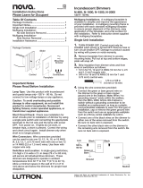
Dimensions
Dimensions for the CLWI-KPLCN are shown in the following illustration.
72 mm
(2.80 in)
72 mm
(2.80 in)
32 mm
(1.24 in)
51 mm
(2.00 in)
51 mm
(2.00 in)
21 mm
(0.82 in)
Additional Resources
Visit the product page on the Crestron website (www.crestron.com)
for additional information and the latest rmware updates. Use a QR
reader application on your mobile device to scan the QR image.
Wiring
Make the Cresnet
®
network NET connection, and then make the optional INPUT
connections to the contact closure(s). Use wire no larger than 1.5 mm
2
(16 AWG). For
details, refer to the illustrations below.
NOTE: The G on the INPUT and NET ports are tied together electronically in the
device.
Earth
CresnetInput
Occupanc
y
sensor
Contact closure
input
D
oorbell
switch
1 2 G
NOTE: The contact closure input has the following rating:
• Digital Input: Rated for 0—24 Vdc, input impedance 200 kΩ, logic
threshold 1.24 Vdc.
• Analog Input: Rated for 0—10 Vdc, protected to 24 Vdc maximum, input
impedance 200 kΩ.
• Programmable 5 volts, 2 kΩ pull up resistor per pin.
Installation
The CLWI-KPLCN can be mounted in a single-gang or multigang electrical box.
Single-Gang Installation
To install in a single-gang electrical box.
NOTE: Electrical box depth must be 35 mm (1.38 in) or deeper.
NOTE: Ensure that system power is off before installation.
1. Push the wires back into the electrical box and fasten the device to the electrical box
with the provided screws.
NOTE: Use care when placing the device in the electrical box. Pinched wires
may cause a short circuit.

2. Attach the faceplate (not included).
3. Ensure that all buttons, including the program button, actuate without sticking.
4. Restore power to the system.
Multigang Installation
In multigang installations, several devices are grouped horizontally or vertically in one
electrical box. When ganging vertically, the devices snap together by sliding the bottom of
the upper device into the top of the lower device. This allows the devices to be mounted
closer together.
For a smooth appearance, a one-piece multigang faceplate (not included) can be installed.
NOTE: The devices do not interlock when ganged horizontally.
NOTE: When installing into a multigang box, do not fully tighten the devices to the box
until the faceplate has been aligned.
Button Functions
The CLWI-KPLCN button functions are based on the control systems program. Refer to
the help le for details.
NOTE: Before using the CLWI-KPLCN, ensure the device is using the latest rmware.
Check for the latest rmware for the CLWI-KPLCN at www.crestron.com/rmware. Load
the rmware onto the device using Crestron Toolbox™ software.
Change Button Assemblies
To change or replace the button assemblies.
1. Squeeze the sides of the button assembly near the center of the device.
2. While squeezing the sides of the button assembly, pull the button assembly off of the
device.
NOTE: When more than one button assembly is installed on a device, press on
one side of the button assembly and carefully remove the button assembly. The
second button assembly can be removed in the manner described in steps 1 and
2 above. Refer to the illustrations that follow.
Remove the Button Assembly
3. Press the new button assembly onto the device. It might be necessary to squeeze
the sides of the button assembly to allow for easier button assembly installation.
Install the New Button Assembly
Troubleshooting
The following provides corrective actions for possible trouble situations. If further
assistance is required, please contact a Crestron customer service representative.
TROUBLE POSSIBLE CAUSE(S) CORRECTIVE ACTION
The keypad does not
function.
The wrong power supply is
being used.
Use a Crestron power supply.
The unit is not receiving
power, or is not receiving
sufcient power.
Verify that the cable plugged
into the NET port is secure.
Verify that the power supply
is correct.
There is a loose connection
in the network.
Verify that the cable plugged
into the NET port is secure.
The keypad does
not function. All six
feedback LEDs are dim.
An improper Net ID is used. Verify that the CLWI-KPLCN
Net ID matches the Net ID in
the program.
The control system power
is off.
Reconnect power to the
control system.
The keypad does not
function, or does not
function as expected.
However, it reports to
the control system with
the proper Net ID.
The unit is not programmed
correctly.
Use SIMPL Debugger to
check the behavior when the
buttons are pressed. Revise
and reload the program
as needed to correct the
behavior.
As of the date of manufacture, the product has been tested and found to comply with specications
for CE marking.
The product warranty can be found at www.crestron.com/warranty.
The specic patents that cover Crestron products are listed at www.crestron.com/legal/patents.
Certain Crestron products contain open source software. For specic information, please visit
www.crestron.com/opensource.
Crestron, the Crestron logo, Crestron Toolbox, and Cresnet are either trademarks or registered
trademarks of Crestron Electronics, Inc. in the United States and/or other countries. Other trademarks,
registered trademarks, and trade names may be used in this document to refer to either the entities
claiming the marks and names or their products. Crestron disclaims any proprietary interest in the
marks and names of others. Crestron is not responsible for errors in typography or photography.
This document was written by the Technical Publications department at Crestron.
©2017 Crestron Electronics, Inc.
Crestron Electronics, Inc. Installation Guide - DOC. 7242B
15 Volvo Drive, Rockleigh, NJ 07647 (2031639)
Tel: 888.CRESTRON 10.17
Fax: 201.767.7576 Specications subject to
www.crestron.com change without notice.
/