Page is loading ...

CLWI-DIMFLVEX
In-Wall 0—10 V Dimmer, 230 Vac
Installation Guide
Description
The CLWI-DIMFLVEX delivers native Crestron
®
control to 0—10 V dimmable xtures or
switched loads in new or retrot 230 volt applications. Featuring reliable inNET EX
®
wireless technology, the CLWI-DIMFLVEX can be installed in virtually any location thanks
to reliable mesh networking. The CLWI-DIMFLVEX delivers a perfect solution for controlling
newer LED xtures from a single gang, without requiring external boosters.
Specications for the CLWI-DIMFLVEX are listed in the following table.
CLWI-DIMFLVEX Specications
SPECIFICATION DETAILS
Load Ratings
Minimum Load
Maximum load
Load types
7 W
2 A/AX; 30 mA sink only per channel
0—10 volt uorescent ballast or LED driver (4-wire)
Power Requirements 220—240 Vac, 50/60 Hz, line power
Environmental
Temperature
Humidity
0° to 40 °C (32° to 104 °F)
10% to 90% RH (noncondensing)
Enclosure 1-gang mountable in a 35 mm (1.38 in) deep square or
round electrical box; gangable in horizontal and vertical
positioning;
requires faceplate (not included)
Dimensions
Height
Width
Depth
72 mm (2.80 in)
72 mm (2.80 in)
32 mm (1.24 in) including front face with buttons
Weight 95 g (4 oz)
Additional Resources
Visit the product page on the Crestron website (www.crestron.com)
for additional information and the latest rmware updates. Use a QR
reader application on your mobile device to scan the QR image.
Important Notes
WARNING: To avoid re, shock, or death, turn off the power at the circuit breaker or
fuse and test that the power is off before wiring!
CAUTION: TO REDUCE THE RISK OF OVERHEATING AND POSSIBLE DAMAGE
TO OTHER EQUIPMENT, DO NOT INSTALL TO CONTROL A RECEPTACLE OR A
TRANSFORMER-SUPPLIED APPLIANCE.
CAUTION: When wiring, refer to the following cautions.
• Install on 10 A branch circuits only.
• Install with 1 x 1.5—2.5 mm² wire complying with BS6004:2000/IEC 60245 and
local electrical codes.
• Use with loads that have a power factor greater than 0.95.
NOTE: LOW-VOLTAGE APPLICATIONS: Operation of a low-voltage circuit with all
lamps inoperative or removed may result in current ow in excess of normal levels. To
avoid transformer overheating and premature transformer failure, Crestron recommends
the following:
• Do not operate low-voltage circuits without operative lamps in place.
• Replace burned-out lamps as quickly as possible.
• Use transformers that incorporate thermal protection or fuse transformer primary
windings to prevent transformer failure due to overcurrent.
NOTE: When wiring, refer to the following notes.
• A neutral connection is required for this device to operate.
• Use copper wire only. For supply connections, use wires rated for at least 75 °C.
• Use only with permanently installed 0—10 volt uorescent ballast or LED driver
(4-wire).
• For use where temperatures are between 0° to 40 °C (32° to 104 °F).
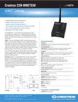
WIRING
Make the power connections to the CLWI-DIMFLVEX. Use 1 x 1.5—2.5 mm2 (14—12 AWG)
wiring when making connections. When making connections, insert the wires into the back
of the unit and use a small at-head screwdriver to tighten the connections.
WARNING: To avoid re, shock, or death, turn off the power at the circuit breaker or
fuse and test that the power is off before wiring!
Tighten the screws
with a small flat-head
screwdriver.
Line
230 Vac
Neutral
Neutral
Earth
Live
+
-
0-10 V
ballast
- +
Load
Conguration
The local buttons must be dened when using the CLWI-DIMFLVEX in Local mode
(operating without a control system). The minimum and maximum dimming levels and the
preset dimming levels can be established.
Dene the Local Buttons
Buttons that are identied as local buttons have predened functions that are described in
the “Default Button Functions” section.
NOTE: Buttons that are not identied as local buttons must be controlled by a control
system.
Dene the local buttons.
1. Press and hold the setup button (located in the lower right corner of the device) for
5 seconds to enter Button Layout mode. The LEDs that correspond to the current
button layout begin to ash quickly. Do not release the setup button.
NOTE: If the setup button is held for 15 seconds without other button presses, the
device restarts. Refer to “Device Reboot” for additional information.
NOTE: If the setup button is released before all buttons are congured, the device
exits Button Layout mode and no changes are saved. The device reverts to the
previously programmed button layout.
2. While holding the setup button, and within 5 seconds of the LEDs starting to ash,
press all of the buttons on the device that require local functionality. Refer to the
“Default Button Functions” section for valid local button options. The LED illuminates
to verify the button press.
NOTE: The device exits Button Layout mode after 10 seconds pass without
additional button assignments. The device reverts to its previously programmed
button layout.
3. Release the setup button.
NOTE: If an invalid button pattern is selected, the button pattern is not saved.
Setting the Minimum and Maximum Dimming Levels
Establish the minimum and maximum dimming levels for the connected loads. To enter
Min/Max Dimming mode:
1. Press and hold the setup button for 10 seconds until all LEDs light and the middle
LEDs begin ashing. The connected load dims to 50%.
NOTE: During Min/Max Dimming mode the device LEDs ash quickly and indicate
the current minimum and maximum dimming levels.
NOTE: The maximum level is saved only if the light level is raised above 75%
(either of the top two LEDs are illuminated).
NOTE: The minimum level is saved only if the light level is lowered below 45%
(either of the bottom two LEDs are illuminated).
2. Press any top button on the dimmer to raise the load to the maximum desired level. If
the connected load begins to cycle or ash, the level must be reduced.
3. Press and hold the setup button for 2 seconds to save the maximum dim level.
4. Press any bottom button on the dimmer to lower the load to the minimum desired
level. If the connected load begins to icker, the level must be increased.
5. Press and hold the setup button for 2 seconds to save the minimum dimming level.
6. Tap the setup button to exit Min/Max Dimming mode.
Setting Preset Levels
The device can recall and store up to three presets, depending on the installed button
conguration and local programming. Buttons that utilize presets are identied in the
“Default Button Functions” section. To set the preset levels, follow the procedure below:
1. Adjust the light level to the desired level.
2. Press the setup button to enter Programming mode. Buttons capable of storing
presets ash their LEDs.
3. Press and hold the desired preset button for about 2 seconds. The LED ashes.
NOTE: If a button is not pressed, the device exits Programming mode after about
5 seconds.
Default Button Functions
The default functionality of a button depends on the button assembly that is installed and
the button conguration determined in the “Dene Local Buttons” procedure.
The illustrations that follow show various button assembly congurations and the default
button press functions. The circled button numbers identify buttons that are congured for
local operation. All other button functions are determined by control system programming.
The button functions for the CLWI-DIMFLVEX are shown below.
Rocker with LEDs on Right (Default Layout)
4
6
1
3
4
6
BUTTON
#
TAP DOUBLE TAP HOLD LED
FEEDBACK
NIGHTLIGHT
LED
FEEDBACK
4 Preset 1 Fast full on Raise Load light level
bar graph
LED glows
when load is off
6 Delayed
off
Fast off Lower N/A -
Rocker with LEDs on Left
BUTTON
#
TAP DOUBLE TAP HOLD LED
FEEDBACK
NIGHTLIGHT
LED
FEEDBACK
1 Preset 1 Fast full on Raise Load light level
bar graph
LED glows
when load is off
3 Delayed
off
Fast off Lower N/A -
Rocker with LEDs on Right with Presets
BUTTON
#
TAP DOUBLE TAP HOLD LED
FEEDBACK
NIGHTLIGHT
LED
FEEDBACK
1 Preset 1 N/A N/A On when
selected
LED glows
when load
is off
2 Preset 2 N/A N/A On when
selected
LED glows
when load
is off
3 Preset 3 N/A N/A On when
selected
LED glows
when load
is off
4 Full on Fast full on Raise Load light level
bar graph
LED glows
when load
is off
6 Delayed
off
Fast off Lower Load light level
bar graph
-
Rocker with LEDs on Left with Presets
BUTTON
#
TAP DOUBLE TAP HOLD LED
FEEDBACK
NIGHTLIGHT
LED
FEEDBACK
1 Full on Fast full on Raise Load light level
bar graph
LED glows
when load
is off
3 Delayed
off
Fast off Lower Load light level
bar graph
-
4 Preset 1 N/A N/A On when
selected
LED glows
when load
is off
5 Preset 2 N/A N/A On when
selected
LED glows
when load
is off
6 Preset 3 N/A N/A On when
selected
LED glows
when load
is off
Single Right Button Control
BUTTON
#
TAP DOUBLE TAP HOLD LED
FEEDBACK
NIGHTLIGHT
LED
FEEDBACK
4 Toggle
Preset 1
/ Delayed
off
Fast full on Cycle
dim
On when load
is on
LED glows
when load
is off
Single Left Button Control
1
2
4
5
6
1
2
3
4
6
1
3
1
2
3
4
5
6
2
BUTTON
#
TAP DOUBLE TAP HOLD LED
FEEDBACK
NIGHTLIGHT
LED
FEEDBACK
1 Toggle
Preset 1
/ Delayed
off
Fast full on Cycle
dim
On when load
is on
LED glows
when load
is off

Operation
Upgrading Firmware
NOTE: Before using the CLWI-DIMFLVEX, ensure the device is using the
latest rmware. Check for the latest rmware for the CLWI-DIMFLVEX at
www.crestron.com/rmware. Load the rmware onto the device using Crestron
Toolbox™ software.
Firmware is upgraded using inNET EX over-the-air rmware upgrades. Refer to the
Crestron Toolbox help le for details.
Restore Default Settings
To reset the device to its factory default settings, send the “restore” console command. All
local programming needs to be reset after restoring default settings.
Device Reboot
Press and hold the setup button for 15 seconds to reboot the device. Release the setup
button after all LEDs on the front of the device ash to full on and then turn off. This
indicates that the device is rebooting. Reboot is completed once the LEDs come back on
to normal operating mode.
Change Button Assemblies
To change or replace the button assemblies.
1. Squeeze the sides of the button assembly near the center of the device.
2. While squeezing the sides of the button assembly, pull the button assembly off of the
device.
NOTE: When more than one button assembly is installed on a device, press on
one side of the button assembly and carefully remove the button assembly. The
second button assembly can be removed in the manner described in steps 1 and
2 above. Refer to the illustrations that follow.
Remove the Button Assembly
3. Press the new button assembly onto the device. It might be necessary to squeeze
the sides of the button assembly to allow for easier button assembly installation.
Install the New Button Assembly
Installation
The CLWI-DIMFLVEX can be mounted in a single-gang or multigang electrical box.
Single-Gang Installation
To install in a single-gang electrical box.
NOTE: Electrical box depth must be 35 mm (1.38 in) or deeper.
NOTE: Ensure that system power is off before installation.
1. Push the wires back into the electrical box and fasten the device to the electrical box
with the provided screws.
NOTE: Use care when placing the device in the electrical box. Pinched wires may
cause a short circuit.
2. Attach the faceplate (not included).
3. Ensure that all buttons, including the program button, actuate without sticking.
4. Restore power to the system.
Multigang Installation
In multigang installations, several devices are grouped horizontally or vertically in one
electrical box. When ganging vertically, the devices snap together by sliding the bottom of
the upper device into the top of the lower device. This allows the devices to be mounted
closer together.
For a smooth appearance, one-piece multigang faceplates (not included) can be installed.
NOTE: The devices do not interlock when ganged horizontally.
NOTE: When installing into a multigang box, do not fully tighten the devices to the box
until the faceplate has been aligned.
Wireless Communications
This device connects to the Crestron network via the inNET EX communications protocol.
Use the procedures outlined below to join or leave an inNET EX network and to verify
communications between the device and the control system.
Joining an inNET EX Network
Before a device can be used in a lighting system, it must rst join an inNET EX network by
being acquired by an inNET EX gateway.
NOTE: A device can be acquired by only one gateway.
1. Put the inNET EX gateway into Acquire mode from the unit itself or from Crestron
Toolbox, as described in the latest version of its manual, which is available from the
Crestron Web site (www.crestron.com/manuals).
NOTE: In an environment where multiple gateways are installed, only one gateway
should be in Acquire mode at any time.
2. Place the device into Acquire mode by doing the following:
a. Tap the setup button three times, and then press and hold it down (tap-tap-tap-
press+hold) until all LEDs on the device ash once (this can take up to 10 seconds).
b. Release the button to start the acquire process. The top two LEDs ash slowly to
show that the device is actively scanning the inNET EX network.
• The top two LEDs turn on for 5 seconds to show that the device has been
successfully acquired to the inNET EX network.
• The top two LEDs ash quickly to indicate that the device was not successfully
acquired to the inNET EX network. Tap the setup button to acknowledge failure
to acquire to the inNET EX network. Ensure that the gateway is in Acquire
mode and within range before attempting the acquire process again.
Leaving an inNET EX Network
To leave an inNET EX network put the device into Acquire mode, as described in “Joining
an inNET EX Network” above, when no gateway is in Acquire mode.
Verifying Communications Status
To check the communication status of the device tap the setup button three times then
press and hold it down (tap-tap-tap-press+hold) for 2 seconds. The top two LEDs ash to
indicate the communication status. Refer to the following table for details.
LED COMMUNICATIONS STATUS
Turns on for 5
seconds
The device is communicating with the control system.
Flashes three
times
The device is communicating with the gateway, but the gateway is
not communicating with the control system.
Flashes twice The device was previously joined to the network but is not
communicating with the gateway.
Flashes once The device is not joined to the network.
As of the date of manufacture, the product has been tested and found to comply with specications for
CE marking.
The product warranty can be found at www.crestron.com/warranty.
The specic patents that cover Crestron products are listed at www.crestron.com/legal/patents.
Certain Crestron products contain open source software. For specic information, please visit
www.crestron.com/opensource.
Crestron, the Crestron logo, Crestron Toolbox, and inNET EX are either trademarks or registered
trademarks of Crestron Electronics, Inc. in the United States and/or other countries. Other trademarks,
registered trademarks, and trade names may be used in this document to refer to either the entities
claiming the marks and names or their products. Crestron disclaims any proprietary interest in the marks
and names of others. Crestron is not responsible for errors in typography or photography.
This document was written by the Technical Publications department at Crestron.
©2017 Crestron Electronics, Inc.
Crestron Electronics, Inc. Installation Guide - DOC. 7240B
15 Volvo Drive, Rockleigh, NJ 07647 (2031637)
Tel: 888.CRESTRON 10.17
Fax: 201.767.7576 Specications subject to
www.crestron.com change without notice.
/