Page is loading ...

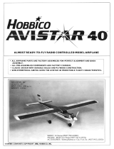
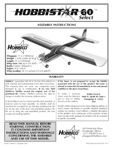
ALMOST READY-TO-FLY RADIO CONTROLLED MODEL AIRPLANE
- ALL AIRFRAME PARTS ARE FACTORY ASSEMBLED FOR PERFECT ALIGNMENT AND
QUICK ASSEMBLY.
- ALL PRE-ASSEMBLED COMPONENTS ARE FACTORY COVERED.
• CLASSIC DESIGN WITH DURABLE BALSA AND PLYWOOD CONSTRUCTION.
• SEMI-SYMMETRICAL AIRFOIL GIVES THE HOBBISTAR 60 AEROBATIC CAPABILITIES.
ENTIRE CONTENTS © 1990,
V1.0

IMPORTANT: BEFORE YOU BEGIN.
If this is your first R/C airplane kit, a word of caution is in order. BEFORE you begin assembly, carefully
took through the box and thoroughly read the instruction manual. Also check the parts list against the items
in the box to be sure you have everything that is on the parts list. Although we have taken great pains to
simplify the building process, there are no shortcuts to safety. These instructions are your guide to safe
and successful flying.
Only after you are thoroughly familiar with the construction process should you proceed with assembly.
Remember! Under no circumstances will a dealer accept a kit back for return if assembly has
already begun.
If the Hobbistar 60 is not quite what you expected, return it to your dealer in New and Unused condition.
However, we think you will agree with us that the Hobbistar 60 kit is one of the finest models of its type and
will offer you many hours of enjoyment.
ADDITIONAL ITEMS
Please check the additional items listed below for those materials not furnished but recommended.
Dubro #163 Wing
seat
tape
........................................
(1)
Dubro#121 E-Z connectors........................................ (6)
or
Goldberg#361 Snap'R'Keepers
...............................(6)
Goldberg#482 1/2" foam
rubber.................................(1)
Dubro #349 Antenna Hook & Keeper.......................... (1)
Devcon #5250 Silicone rubber 2 oz. ...........................(1)
Hobbico (HCAR3950) Bullet 30 min. epoxy 9 oz. ....... (1)
Hobbico (HCAR3760) Bullet Threadlock..................... (1)
Arco#64 Rubberbands 1/4 lb. ...................................(1)
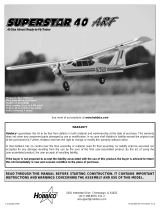
A four channel radio control system with 4 servos is required for the
Hobbistar 60. The various components are pictured above.
Most engines require a 1.5V glow plug starting battery, a glow plug clip,
and a quality brand fuel (consult the engine manufacturer's recommenda-
dons).
Here are a few tools that are necessary to properly finish this kit. They
should be available from your local hobby dealer or hardware store.
-2-
A quality brand engine will be needed. We recommend the O.S. 60FP two
cycle engine. Also a prop and fuel tubing will be required for the engine.

1.
Right Wing..............................................................................
1
2.
Left
wing
.....................................................................1
3.
Fuselage
....................................................................
1
4.
Vertical stabilizer and rudder
......................................1
5.
Horizontal
stabilizer
and
rudder
..................................1
6. Wing
joiners................................................................3
7.
Wing
mounting
dowels................................................
2
8. Fuel tank compartment
cover.....................................
1
9. Front steerable nose
gear...........................................
1
10. Main
landing
gear
.......................................................2
11. Tires and wheels
........................................................3
12. Fuel tank
....................................................................
1
13. Neophrene
ring....................................................................
1
14. Plastic
disk........................................(1)
large
(1)
small
15.
Clunk weight...............................................................
1
16. Fuel
pipe
....................................................................3
17.
m3
x
18
self-tapping screw
.........................................
1
18.
Silicone
fuel
line..........................................................
1
19. Center
tape.................................................................
1
20. Servo
tray.......................................................................
1
21. Aileron servo
tray........................................................
1
22.
Spinner
(not shown)
...................................................1
23. Stabilizer control rods
.................................................2
24.
Aileron
control
rods
(7
7/8")
........................................2
25. Throttle and nose gear control rods (17 3/4")
..............2
26. Plastic guide tubes
.....................................................2
27. Clevis
.........................................................................4
28. Control horns
..............................................................2
29. Control horn back plate
..............................................
2
30.
4mm
x
10mm
collars
..................................................3
31.
m3
x4 screw
..............................................................7
32. Nose gear control horn
...............................................
1
33.
m4
x
15
screw
............................................................8
34.
m2
x
20
screw
............................................................4
35.
m3
x
8 screw
..............................................................
1
36. Tank
Cap....................................................................
1
37.
m2x 12 self
tapping
screw
.........................................4
38.
m4
lock washers .........................................................8
39.
m4
nut...............................................(4)
small
(4)
large
40.
Landing
gear
straps....................................................
2
41.
Aileron control horns
...................................................2
42.
Aileron servo
tray
blocks.............................................
2
43.
Alignment peg ............................................................ 1
44. Engine mounting pads
................................................2
45. 5mm
x
10mm
wheel collars
........................................4
46. Clevis retainer tubing
..................................................1
-3-
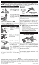
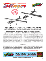
Before assembly match the parts in the exploded view of the Hobbistar with the parts in the kit. Check off each part
on the parts list. If any parts are missing or damaged return the kit to your hobby dealer.
PARTS LIST

PRE-ASSEMBLY
1. Locate part #6 wing joiners. Join the three wing joiners together
using a light coat of epoxy. They should form a "V" shape as shown
above.
4. Locate the #4 vertical stabilizer and #5 horizontal stabilizer. The
rudderis temporarily attached to the vertical stabilizer. The elevator
is temporarily attached to the horizontal stabilizer. Remove the
rudder, elevator, and the preinstalled metal hinges.
2. Assemble the aileron support tray with parts #21 aileron servo tray
and #42 10mm x 37mm balsa aileron servo tray blocks. Epoxy the
balsa blocks to the plywood tray as shown above.
5. Apply a small amount of vaseline along the hinge point on both sides
of the hinge. This will prevent epoxy from getting in the hinge joint
and ruining the hinge. Do not get vaseline on the rest of the hinge.
If this happens the epoxy will not hold the hinge and the aileron may
separate from the wing causing a crash. Do this step to all eleven
hinges.
3. The ailerons are mounted temporarily from the factory. Remove the
ailerons from the wings. Now remove the three metal hinges on each
wing.
6. Apply epoxy to both sides on one end of the hinge as shown. Slide
the hinge back into the slot in the wings trailing edge. Wipe off any
excess epoxy before it cures. The hinge pin must be against the
trailing edge of the wing to allow the ailerons, installed later, to fit
correctly. Install six hinges, three in each wing, and set the wings
aside until the epoxy cures.
-4-

7. Using the same procedure for epoxying the hinges that was used in
Step 6, epoxy the three hinges into the horizontal stabilizer. Epoxy
two hinges into the vertical stabilizer.
10. Remove the aileron and apply epoxy to the hinges and the part of the
torque rod that is inserted into the aileron. Also force a small amount
of epoxy into the torque rod hole that is in the aileron. Carefully install
the aileron onto the hinges and torque rod. Install the ailerons
onto both wings carefully. Make sure that no epoxy gets into the
torque rod hinge. Also be sure that there are no gaps.
8. After the epoxy holding the hinges has cured, locate the ailerons that
were removed from the wing in Step 3. Test fit the aileron on the
wing. Be sure the torque rod fits in the hole in the edge of the aileron.
The torque rod is what will transmit motion from the servo to
the aileron.
11. Install the rudder on the vertical stabilizer and elevator on the
horizontal stabilizer using the same procedure used for the aileron.
Be careful not to leave a gap at the hinge.
9. With aileron temporarily installed, there should be no gap. If the
plane is flown with a hinge gap of more than 1/16", flutter (a rapid
vibration) may be created. This flutter may cause the ailerons to
come loose or in severe cases, break the wing.
12. Coat the fuel tank compartment with an even thin coat of epoxy.
Coverall exposed balsa and plywood parts. Be careful not to fill any
holes. Also at this time coat the bottom of the #8 fuel tank
compartment cover. This will prevent the fuel from destroying the
- 5 - wood.

WING JOINER INSTALLATION
1. Using the wing joiner assembled in Step 1 of pre-assembly, insert
the wing joiner into the wing panel temporarily. Also install the wing
#43 alignment peg as shown. Do not glue at this time.
CAUTION:
Make sure that the glue joints at the wing root are fastened
securiy. Check the ribs and the sheeting. If this is at all loose, apply
epoxy between the rib sheeting and spars.
4. When you are satisfied with the fit of the wing joiner, remove the
wings from the joiner. Mix a batch of 30 minute epoxy and using the
right wing panel (has Hobbistar on top) smear the inside of the right
wing joiner pocket with a heavy coat of epoxy. Also coat half of the
wing joiner with
epoxy
and push
into
the wing joiner pocket.
Coat
half
of the wing alignment peg with epoxy and insert it into the hole at the
rear of the wing root. Clean the epoxy from the wing root to prevent
epoxy build up. Allow the epoxy to cure.
2. Slide the other wing panel onto the wing joiner. Slide the two wing
halves together. Check for proper alignment. There should be no
gap between the wing halves. If there is, trim the end of the wing
joiner slightly to allow proper fit. Do not glue at this time.
Bottom of
Wing
5. Mark the location on the bottom of the wing where the wing joiner is
installed.
3. The wing should form a "V" when assembled as shown. The top of
the wing has lettering on it. When one side is placed flat on your
work surface, the other wing tip should be angled up so there is
approximately 2" of clearance between the surface and the tip.
-6-
6. When the
epoxy
has
cured
you
may
proceed
to
join
both
wing
panels
together. Mix a batch of epoxy and heavily coat the wing joiner
pocket
of
the
left wing.
Also
apply an
even
coat
of
epoxy
on
both wing
roots. Be sure to cover the whole wing root. When satisfied with the
gluing, slide the wing panels together and check for fit. Wipe excess
glue from the joint. IsopropyI alcohol works well for this. It is best to
use masking tape to hold the wing halves together until the epoxy
cures.

Note: You may proceed with fuselage preparation and come back to here
after the wing is ready.
7. After the epoxy has fully cured (overnight) remove the masking tape
and apply the blue center tape. Begin at the bottom trailing edge,
wrap forward and around to top trailing edge overlapping the begin-
ning point.
3. Remove the servo tray and, following the picture, remove the
covering from area "A".
AILERON SERVO
TRAY INSTALLATION
4. Then
remove
the balsa
wood
from
area
"B".
Remove
enough balsa
wood to accommodate the servo previously measured in Step 1
1. Locate the pre-assembled #21 aileron servo tray with #42 balsa
blocks and a servo from your radio system. Slip the servo into the
tray and measure the distance from the bottom of the servo to the
bottom of the balsa block. Note the distance for use in Step 4.
2. Remove the servo from the servo tray. Turn the servo tray upside
down (balsa blocks up) and lay the end of the tray on the line drawn
in Step 5 of the wing joiner installation. Using a felt tip pen trace
around the outside and inside of the servo tray.
5. Set the servo in the servo tray and test fit the servo tray to
the mounting area. When satisfied with the fit, remove the servo and
epoxy the servo tray to the mounting area.
-7-

FUSELAGE PREPARATION
1. On the side at the rear of the fuselage use your finger to locate the
stabilizer cutouts. They will be soft spots under the covering on both
sides. Using a sharp knife remove the covering material from the soft
spots on both sides. During the process you will find a balsa tail post.
This must also be removed to allow the installation of the horizontal
stabilizer.
2. Again using your finger locate the vertical stabilizer slot on top of the
fuselage, and remove the covering from this area.
3. The factory has precut the rudder and elevator control rod exit holes.
These are approximately 1/8 inch by 1 inch long. The location
of the rudder exit hole is approximately 61/2 inches forward from the
tail post and on top of the fuselage and slightiy to the right when
viewing the plane from the tail. The area appears slightly darker.
Remove the covering from this area at this time. -8-
The elevator exit hole is located on the left side of the fuselage,
61/2" forward of the tail post and approximately 1 inch above the
bottom of the fuselage. You may be able to detect this as a soft spot
in the fuselage. Remove the covering from the elevator exit hole.
5. The wing dowel holes are also pre-drilled. They are located in the
area indicated in the photo. Using a sharp knife remove the covering
material at this time. There are four holes, two on each side of the
fuselage. Insert the dowels so that they protrude equal distance on
each side of the fuselage. Epoxy part of the dowel protruding from
the sides of the fuselage. This will keep fuel
from
ruining
the
dowels.
6. The main landing gear slot is located on the bottom of the fuselage,
approximately 171/2 inches back from the nose (or front) of the
plane. Using a sharp knife remove the covering from this area.

STABILIZER PREPARATION
1. Locate the horizontal stabilizer. Slide the stabilizer into the slot
prepared in the previous section. Position the stabilizer so that it is
centered in the fuselage and that the trailing edge of the elevator is
90' to the center line of the fuselage. Insert a pin through a piece of
string and attach the pin to the fuselage on the center line as shown.
Stretch the string to the comer of the elevator. The distance from the
pin to the comer must be equal on both sides. This method will adjust
the stabilizer so it is 90' to the center line of the fuselage.
2. Mark on the stabilizer where the fuselage and the stabilizer touch.
Do this on the top and the bottom of the stabilizer. Remove the
covering in between the
two
lines. This will allow a
more
secure glue
joint when the stabilizer is epoxyed later. Do not cut the balsa wood
under the covering.
3. Locate the vertical stabilizer. Remove the covering from the lower
vertical stabilizer base.
INSTALLATION OF
HORIZONTALSTABILIZER
IMPORTANT: This next series of steps will determine how well your
Hobbistar 60 will fly. So please read and reread these steps so that you
are totally familiar with its sequence.
1. Using wing saddle tape, apply a strip to both sides of the wing
saddle area as shown.
2. Using four rubber bands (#64) temporarily secure the wing to the
fuselage. This becomes your basic reference point.
3. Lay the fuselage with wing attached on any flat surface. Mix a batch
of 30 minute epoxy. You will have plenty of time to work so don't
hurry. Using a scrap piece of plywood left over from the aileron servo
tray, apply a generous amount of epoxy to the inside area; top and
bottom, and along the sides of the stabilizer slot as shown.
-9-

4. Using the same scrap of plywood, apply an even coat of epoxy to the
top and bottom of the horizontal stabilizer in the area where you
removed the covering.
INSTALLATION OF VERTICAL STABILIZER
Now if we have done a good job with the wing-stabilizer relationship, the
installation of the rudder should be easy. The vertical stablilizer is 90' to
the wing. A drafting triangle would be helpful here.
5. Slide the stabilizer into the slot from the rear. This fit should be close
but not tight. Using a ruler (12") check to see if you have equal
distance from the center of the tail to the outside edge of the stab.
Now using the string explained in the stabilizer preparation section,
adjust the stabilizer so it is 90' to the center line of the fuselage.
1. Looking into the fuselage vertical stabilizer slot, apply some epoxy
to the top surface of the horizontal stabilizer that is visible inside the
fuselage.
2. Mix a small batch of epoxy and apply it to the area inside of the
fuselage on the surface of the exposed wood. Apply an even coat
to the vertical stabilizer base where you removed the covering. Inset
the vertical stabilizer into the slot and push down until the stabilizer
stops.
6. Now view the stabilizer-wing relationship from behind with the plane
resting on a level surface (see photo above). Distance
"x"
should be
the same. If not, shim the stabilizer using a small sliver of wood to
get the proper relationship. Let the epoxy cure thoroughly.
3. Using the triangle, check to see if the rudder is 90* to the horizontal
stabilizer. If so, a couple of straight pins will hold the rudder in
position until the epoxy cures.
-10-

MAIN LANDING GEAR INSTALLATION
Place a small bead of silicone sealant in the groove, then insert the
landing gear strut into the fuselage in the holes on the bottom as shown.
Secure the struts in place with the metal straps and m3 x 10 self-tapping
screws.
NOSE GEAR CONTROL ROD
1. Drill a 1/8" hote in the fuselage bottom right side ata 30' angle so that
the drill also drills through the front fuel tank mount, insert the
17 3/4" x 1 /16" rod through the holes and mark where the rod hits the
rear fuel tank mount. Remove the rod. Cut a white tube to 11" and
rough it up with 240 grit sandpaper. Drill a 1 /8" hole where you made
the mark in the rear fuel tank mount. Insert the white plastic tube
through the holes so that the end of the tube is even with the bottom
of the fuselage. Epoxy the tube to the fuel tank mounts and the
bottom of the fuselage.
2. Install the nose gear control horn parallel to the nose gear axle and
tighten the mounting screw. Next install a 4mm x 10mm collar on top
of the control horn and secure with a m3 x 4 screw.
- 11
-
3. If using the Snap 'R' Keeper make a 90" bend 5/16" from the end of
the 17 3/4" control rod as shown. If using the E-Z connector, install
the connector on the bottom of the nose gear control horn following
the manufacturer's instructions.
4. Slide the nose gear shaft through the nose gear mount. Secure the
gear in place with a 4mm x 10mm collar ana m3x 4 screw. Slide the
17 3/4" control rod into the white tube in the bottom of the fuselage.
Connect the rod to the nose gear control horn using the Snap'R'
Keeper or E-Z connector following the manufacturer's
instructions.
WHEEL INSTALLATION
Install awheel on the nose gear. Then install a 4m m x 10m m wheel collar
and secure it with a m3x 4 screw. Install a 5mm x 10mm wheel collar on
each side of the main landing gear. Then install the wheels and then the
other 5mm x 10mm wheel collar. Secure the wheel collars with the m3 x
4 screws. All three wheels should turn freely. If not, trim the inside of the
wheel slightly.

ENGINE INSTALLATION
1. Temporarily install the two mounting pads to the engine mount using
four 4mm x 15mm screws. Set the engine on the mounting pads so
that the center line of the engine is in line with the center line of the
engine mount. Also the drive washer on the engine must protrude
1/8" from the front of the plane. Next, mark the mounting holes for
the engine on the pads.
2. Remove the pads and drill a 5/32" hole at each mark.
4. Make a "z" bend in the 17 3/4" throttle control rod and install on the
throttle arm of engine. Next, cut one white tube so it is 9" long. Rough
it up slightly with sand paper. Now epoxy it inside of the fire wall and
to the fuselage former as shown (You may have to drill the hole
completely through the firewall).
5. As you install the engine and mounting pads on the engine mount,
slide the throttle control rod into the throttle control tube. Install the
four lock washers. Note: It is advisable to use semi permanent
thread locking compound on the screws.
ASSEMBLY OF FUEL TANK
3. Mount the engine to the mounting pads by using four 4mm x 15mm
screws, four lock washers and four 4mm nuts (small) as shown.
1. Assemble the fuel tank as shown. Apply a bead of silicone sealant
around the fuel tank cap as shown when installing it into the fuselage.
-12-

RADIO INSTALLATION
2. Wrap the fuel tank with natural foam to insulate it from vibration.
Install the fuel tank so that the cap is through the hole in the firewall.
Install two six inch pieces of fuel tubing to the fuel pipes from the fuel
tank. Connect the
tubing
from
the
line
with the clunk
weight attached
(called the fuel pick-up line) to the carburetor. The other line is
connected to the muffler pressure tap in the next step.
3. Install the muffler following the manufacturer's instructions. Connect
the pressure line to the muffler pressure tap. You may need to trim
the fuselage side to allow muffler clearance.
1. Using your radio switch as a guide, make the necessary opening for
mounting the switch on the left side of the fuselage, as viewed from
above looking toward the engine, and 2" down from the wing saddle.
Install the switch at this time. Mounting the switch on this side will
prevent fuel from damaging the switch.
2. Test fit your servos into the servo tray. Trim the tray as necessary
to fit. If over-sized servos are being used, it may be necessary
to make an additional servo tray. We recommend using standard
to heavy duty sized servos. Arrange them as shown in the picture
above. Before securing the servos to the servo tray, read the
instructions that came with your radio on how to install the servos.
4. Set the hatch cover over the fuel tank compartment. Drill four 1/16"
holes as
shown. Secure the hatch using
four 2.6mm
x
12mm
screws.
3. Mount the servo tray onto the rails inside the rear of the fuselage.
Epoxy the tray in place. Use enough glue to hold the tray in place,
but be very careful not to glue the servos to the tray or the fuselage.
-13-

4. Plug the servos and switch into the receiver and the receiver battery
into the switch. Then wrap the receiver and the receiver battery in
natural foam. Use the rubber bands to loosely hold the foam in place.
This foam packing protects the radio components from damaging
engine vibrations. Place the battery toward the front of the
compartment.
CONTROL HORN INSTALLATION
1. Caution: When installing control horns the center line of the control
horn holes must be the same as the center line of the hinge joint. If
not the control surface will move farther one way than the other.
PUSH ROD INSTALLATION
1. Insert the threaded end of the rudder pushrod into the fuselage;
working it around until the end of the push rod is extending through
the exit hole on the top of the fuselage. This may take some time.
Cut a piece (3/16") from the retaining tube and slide onto the rod,
2. Mount the rudder control horn so that it is on the center line of the
hinge joint and pointing toward the push rod as shown. Mark the
location of the two mounting holes and drill a hole on the marks.
Insert the m2 x 20 screws through the horn and into the control horn
back plate. Attach the clevis to the control horn. Slide the retaining
tube over the clevis to secure it.
2. Insert the threaded end of the elevator pushrod into the fuselage;
working it around until the end of the rod i s extending through the exit
hole on the left lower side of the fuselage. This may take some time.
Cut another piece (3/16") from the retaining tube and slide onto the
rod. Install the nylon clevis onto the threaded end of the push rod.
14-
3. Mount the elevator control horn on the elevator so it is on the elevator
hinge joint center line and pointing toward the elevator pushrod.
Using the same procedure as before, install the m2 x 20 screws and
control horn back plate. Attach the clevis to the control horn. Slide
the retaining tube over the clevis to secure it.

CONTROL ROD ADJUSTMENT RADIO INSTALLATION
1. Be sure that your radio system is fully charged and the servos are
plugged into the receiver. Turn on the transmitter then receiver. Set
the trim levers to the neutral position. Turn the receiver then the
transmitter back off.
4.
If
using the
Snap
'R'
Keeper mark on the push rods
where
the hole
in the servo arm is.
2. Adjust the servo arms so that they are positioned as shown above.
The screw holding the arm on may need to be removed so that the
arm can be removed and adjusted.
5. Make a 90' bend at the mark on the push rods. Cut the excess wire
as shown,
and
install the Snap
"R"
Keepers
to
the rod and servo
arms
following the manufacturer's instructions. If using E-Z connectors
install them on the servo arms and attach the rods following the
manufacturer's instructions.
3. Set the rudder and elevator so that they are in the neutral position as
shown.
6. With the transmitter and receiver on, set the throttle to full speed on
the transmitter. Set the throttle arm on the carburetor to full power.
Install the push rod as instructed in the previous step. Next, install
in order the spinner back plate, prop, prop washer, prop nut, and the
spinner. Use the two 2x12 self-tapping screws to secure the
-15- spinner.

AILERON SERVO INSTALLATION
1. Route the servo wire through the side of the tray as shown. Using
the screws supplied with your radio, mount the servo into the tray.
Install the clevises on the threaded ends of the aileron control rods.
Connect the control rods to the aileron horns. Center the aileron
servo arm and measure the length of rod needed. Use the same
procedure to connect the aileron control rods to the servo arms as
used in control rod adjustment Step 5. Uneven aileron centering will
cause severe turns.
2. Turn both the transmitter and receiver switches on. Center the trim
levers on the transmitter. Rotate the clevises in the proper direction
to center the control surfaces (clockwise - shortens the length). The
rudder should have 1" of throw to each side. The elevator 1/2" up and
1/2" down.
3.
If
the receiver antenna should
get
caught, the receiver could possibly
be damaged. By putting a strain relief on the antenna the damage
may be prevented. Cut an arm off of a servo arm as shown above
and thread the receiver antenna through the three holes. Position
this about 6" from the receiver.
4. Drill a 1/16" hole in the side of the fuselage and the upper portion of
the vertical stabilizer. Install the strain relief close to the receiver. Route
the receiver antenna through the holes as shown. This configuration
should allow for the best radio reception. Move the strain relief up to the
hole in the fuselage. Leave some slack in the antenna between the
receiver and the strain relief. Do not cut the antenna. Make another
strain relief to hold the antenna to the tail.
At this time be certain that the aileron servo is connected to the receiver,
otherwise the wing will need to be removed later to connect it. The wing
is mounted to the fuselage by using (8) #64 rubber bands. Wrap the bands
around the wooden dowels as shown above. This design is to allow for
those not-so-penect landings that come with learning how to fly. The
bands are designed to pop off during hard landings and thus help prevent
major damage. Four rubber bands are needed per side.
CENTER OF GRAVITY
The center of gravity is a very important aspect of setting up the airplane
property. It will control a large part of what type of flying characteristics
your plane will have, if it is nose heavy the airplane will try to dive, and the
elevator will be sluggish to respond to your control inputs. If the plane is
tail heavy the airplane will be very sensitive to the elevator and possibly
uncontrollable. The center of gravity should be checked with the fuel tank
empty in the plane to be accurate. The range in which the airplane should
balance is 3 1/2" to 4" back from the leading edge of the wing. With
standard radio equipment, the plane should balance within this range. If
it does not balance within this range, feel free to add weight to the nose
or tail as you need to obtain proper C.G.
RADIO CHECK
Always check the operation of your radio before you fly to see that the
control surfaces move in the proper directions and that they move the
proper amount. If the direction of rotation needs to be reversed to correct
for reversed controls, simply change the side of the servo arm to which the
push rod is attached. To INCREASE the amount of movement that the
surface will have, move the CLEVIS CLOSER to the surface or move the
(SNAP 'R' KEEPER OR E-Z CONNECTOR) away from the center of the
servo arm.
To
DECREASE
the
amount
of
movement,
move
the
CLEVIS
AWAY from the surface or move the (SNAP 'R' KEEPER OR E-Z
CONNECTOR) closer to the center of the servo arm.
-16-

STARTING ENGINE
Engine Maintenance
Always check the engine mounting bolts, muffler, glow plug, propeller and
spinner, etc., before attempting to start the engine. Check for loose bolts,
nuts
or
screws which
may come
off
when the
engine
is
running and cause
serious damage. Always check the area in which you will be flying or just
running the engine. Check for possible hazards, such as loose rags,
rocks, tools, etc., lying on the ground which may get caught in the prop.
If you intend on starting the engine by hand flipping the prop, always use
a chicken stick, and be sure to check the position of the prop. It is most
comfortable when it is at the 2 o'clock position when starting the
compression stroke.
When
you
are using an
electric
12V
starter, the
position of the prop is of no concern.
Engine Break-In and Starting
Most manufacturers recommend that the engine be broken-in on a test
stand. We also recommend that this be done according to manufacturer's
instructions.
If
a
test
stand
is
unavailable the engine may be broken-in on
the Hobbistar. Breaking-in the engine allows the parts to "seat to each
other.
1. Remove the carburetor fuel line and the muffler pressure line from
the muffler.
2. Fill the fuel tank through the carburetor fuel line; when the tank is full
the fuel will come out the pressure line.
3. Reconnect the tubing.
4. Follow your manufacturer's instructions according to needle valve
settings.
ENGINE TROUBLESHOOTING GUIDE
SYMPTOM
The engine does not start.
The propeller is difficult to
rotate.
The engine fires but does
not start.
The engine starts but does
not sound or run good.
-17-
POSSIBLE CAUSE
Glow plug battery is making poor contact.
Battery is dead or has a very low voltage.
Bad glow plug (burned up or deteriorated
filament).
Improper air/fuel mixture intake.
Engine is flooded with fuel.
Engine may be flooded.
Fuel is not reaching the carburetor.
Improper break-in procedures.
Loose plug or bad plug.
5. Turn the radio on and open the throttle to full open Place your finger
over the air intake on the carburetor while turning the prop counter
clockwise a few time? Notice the fuel line It no fuel is reaching the
carburetor, recheck the fuel line plumbing
6. Reduce the throttle to 1/4 or 1/2 throttle for stalling
7. Using a starting stick (chicken stick) and holding the fuselage firmly,
quickly flip the prop in the counter clockwise direction Do not attach
the
glow
plug
clip
in
this
step
This
will
prevent
the
engine
from
being
flooded and will make starting much easier Do not use bare hands/
fingers for starting, as the kick back from a model engine can be
strong enough to cause severe injury
8. Attach the glow plug clip at this time
9. With quick flipping movements, flip the prop in the counter-clockwise
direction If the engine does not try to start in the first few tries, double
check your procedure and keep trying
10. Once the engine has started, listen carefully to the sound of the
engine The sound of the engine will tell you how the engine is
running,
if
you
know
what
to
listen
for
A
lower
tone,
popping
sound
is the sound of a rich running engine As you turn the needle valve
in, the popping sounds should decrease and the pitch of the engine
should rise The optimum needle valve setting will depend on your
engine. Again check with the manufacturer's recommendations for
engine break in procedures and valve settings
11. If you continue to have problem s with the performance or starting of
yourengine, refer to engine trouble shooting guide as shown below
SOLUTION
Check to see if the battery is wired correctly and to
see if the clip is making good contact with the plug.
Replace or recharge the battery and check to make
sure the battery can glow the plug red hot prior to
starting.
Replace the glow plug.
Prime the engine through the carburetor air intake.
Close the needle valve completely and try to start
the engine. It should start and then quickly stop.
Reset the needle valve and continue starting.
Remove the glow plug and rotate the engine until
only a mist of fuel remains in the cylinder. Replace
the plug and continue.
Check the level of fuel in the tank. Recheck fuel.
Open the needle valve a half turn or so and continue.
Check the break-in procedure and repeat.
Replace the plug and/or tighten the old plug.

Pre-Flight Check
1. Clean the dust dirt, and oil off of the surface of the airplane.
2. Check to make sure all nuts, bolts, and screws are securely
fastened.
3. Check all control surfaces to see if they are properly attached.
4. Check the range of the radio system as the manufacturer
recommends.
5.
Check
that all controls move
smoothly and
in the
proper
directions.
6.
Check
the level of charge in
the
transmitter and receiver batteries.
7. Check that the area being used is free of obstacles and debris.
8. Check the frequencies currently in use at the field and in your
area.
9. Check the level
of
the fuel tank
to
be sure
it
is
full.
10. Double check the radio operation.
Flight Safety
• If this airplane happens to be your first radio controlled airplane, we
strongly suggest that you ask a skilled pilot or instructor to help you
learn how to fly. You should also suggest to him to take the maiden
flight to see what problems (if any) that need to be worked out. There
will be enough to worry about on your first solo flight without having
to worry about whether or not it is properly set up.
• Fly in an open field without any obstructions. For example, trees,
power lines, buildings, crowds of people, etc., are obstacles that the
plane may hit and cause damage.
• If you are a novice pilot, local area clubs have been formed and are
very willing to help you with any questions you may have. Many of
the clubs even have club trainer airplanes that they will actually teach
you
to
fly
with.
This helps prevent
disappointing
crashes on
your first
flights. Addresses of local area clubs can be located from your local
area hobby shop and/or by writing to: Academy of Model Aviation,
1810 Samuel Morse Drive, Reston, VA 22090.
• Fly the model at reduced throttle until you get to know the flight
characteristics.
• When adjusting the needle valve just prior to flight, hold the plane at
a 45* nose up altitude, full open throttle and adjust the throttle for top
performance as the manufacturer's instructions suggest.
Take-Off
The airplane may be taxied around on a smooth/open section of
pavement without the wing after the engine has been adjusted and the
radio has been properly checked. Become familiar with controlling the
plane on the ground with the rudder, in the air you will find that most of the
time you will be using a combination of elevator and ailerons to turn the
plane because they are more effective in the air. On the ground, the
rudder is more effective. A transition will need to be made once the plane
leaves the ground. That transition, from using the rudder on the ground
to using the ailerons once it leaves the ground, will take a little practice.
One good rule of thumb is to always take off directly into the wind (if there
is any). This will prevent the wind
from
trying
to
blow the model
from
side-
to-side and will not take as much runway as if you were trying to take off
downwind.
Once you feel comfortable with the way it handles on the ground, it
comes
time
for
you
to
concentrate
very
much
on the
airplane's
movements.
As you are ready for take-off, simply point the nose into the wind and
slowly advance the throttle up to full throttle. At this point the plane will be
going very fast and will be very sensitive to your rudder inputs. Use
smooth inputs
to
correct the plane
from
wandering
off
of
the runway. Once
the plane is at take-off speed, slowly pull back on the elevator stick. This
will cause the plane to leave the ground. At this point, notice whether the
plane tends to turn, climb or dive, and make the necessary opposite
control inputs to keep the plane on a gentle climb in the desired direction.
Flight
Once the plane has reached a safe altitude, reduce the throttle to
about half power. If the airplane is properly set up (i.e. correct C.G., trims
all
centered,
engine properly set), the plane should be
very
stable without
any wandering tendencies. It the plane does tend to go more in one
direction than another, use
your
trim levers on
your
transmitter
to
correct
this. Do not look at the transmitter while adjusting trims. Then while the
plane is flying straight, adjust the elevator trim to correct abnormal
climbing or diving. If the trims will not overcome a turn or a climbing
tendency, land the model immediately and check for improper setup.
Landing
There is an old saying that states, "You do not have to take off...
But you do have to land." Therefore, be ready to land at all times during
your flight. The engine may not stay running through a complete tank of
fuel for one reason or another. It is suggested to time the "run time" of a
complete tank before flight. That way you know approximately what to
expect and when you need to land before the fuel runs out.
Set up your landing approach downwind at 100-200 feet up and 500-
800 feet away depending on the height
of
the plane and the strength
of
the
wind. Approach into the wind and slowly reduce the throttle to the closed
position. Concentrate on the glide path of the plane, taking notice of
whether the plane will reach the beginning of the runway or if it will
overshoot the runway completely. With smooth, deliberate inputs, use
your engine power and your elevator to adjust the glide path so the plane
will touch down smoothly on the beginning of the runway at its slowest
speed. It will still seem very fast and will use the complete runway to slow
down.
After-Flight Maintenance
• Remove all excess fuel from the fuel tank as this fuel can become
jelly-like and cause clogging of the fuel lines as well as clogging the
engine's carburetor valves.
• Always use after-run oil in the engine to prevent corrosion.
• Check and double check that the transmitter and receiver switches
are switched to the off positions.
•
Wipe
off
the
excess
oil that will collect on the
wing
and
fuselage.
Use
a light-duty cleanser to help cut through the oil.
• Remove fresh fuel from the surface of the plane immediately as
different brands can cause clouding of the surface.
• Replace any bent, marred, or dinged props as they can fly apart at
any time when the engine is turning.
• Completely check the aiplane for damage to the wings, landing gear,
covering and repair as needed before your next flight.
Repair
If damage should occur, wipe the broken area clean with a clean rag to
remove all debris. Use epoxy glue to repair. Do not use Cyanoacrylate
adhesive near any foam parts as it will deteriorate the foam.
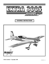
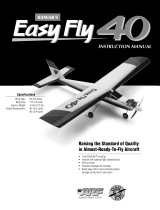
Fully Assembled Hobbistar 60
-18-

YOUR FIRST FLIGHT
Pre-Flight Checklist
Before leaving for the flying field go through the pre-flight checklist
This will help prevent you from forgetting to take things with you.
A. Make sure the transmitter and receiver battery packs are fully
charged. One way to check is by using a Hobbico voltmeter.
B. Transmitter, make sure it is the same frequency as the receiver.
C. Glow plug clip and fully charged 1 1/2 volt battery.
D. Fuel and fuel pump or fuel bulb.
E. Rubber bands #64.
F. Extra props.
G. Screw driver and knife.
H. Epoxy and something to mix it on.
I. Paper towels (to clean the plane).
FLIGHT DIRECTIONS
Before starting the engine check and make sure all screws are tight, that
the hinges have not come loose, the control surfaces move in the right
directions according to your input on the transmitter, and nobody is on
your frequency.
1. Start the engine and set the needle valve following the engine
manufacture's instructions.
2. Hold the plane tightly and move the throttle to full speed. Pick the
plane up and hold it at a 45'-60' nose up for 10-15 seconds. The
engine should run smoothly. If it starts to die the engine is either too
rich or too lean and the needle valve needs readjusting.
3. Taxi the Hobbistar to the end of the runway and point the nose into
the wind.
4. Check that the control surfaces respond
to
the
transmitter commands.
5. Gently advance the throttle to full power.
6. Gently steer the plane left or right as necessary to obtain a straight
take-off.
7. After the plane has gained speed, gently pull back on the elevator
stick. Do not allow the plane to climb too steeply.
8. Keep the wings level and reduce the throttle some to obtain a gentle
climb.
9. To turn, gently move the aileron stick to the side and pull back on the
elevator. If too much aileron is used the plane will bank too steeply.
Make a wide, gentle turn. When the turn is completed, return the
sticks to the center.
10. After the plane passes by you make another wide 180' turn.
11. When learning to fly it is easier to control the plane by facing the
direction the plane is going and looking over your shoulder at it.
12. Fly in a figure eight making left and right turns at the end of
the straights.
13. For the first landing don't worry about landing on the runway, just try
not to hit any objects. Decide where you are going to land and gently
turn into the wind 500-800 feet down wind.
14. When you know you can reach the landing area, reduce the throttle.
You want the plane to gently descend towards the landing area.
Keep the wings level and do not allow the nose to rise. This can
produce a stall (a lack of lift) and the plane will dive steeply.
15. If the plane is going to be short of the landing area apply some
power to reach the landing area. If the plane is too high, apply power
and climb back up to some altitude and set-up to land again. With
practice you will be flying with more confindence and able to make
nice smooth landings on a runway. The only way to become a good
pilot is to practice.
Hobbico Inc. is proudly known as being the nation's number ONE
supplier for ARF type airplane kits. Below are a few of the fine kits
that are available from your dealer.
HCAA2560 - Diabolo
HCAA2570 - Super Chipmunk 40
HCAA2510 - Super Chipmunk 25
-19-

ASAP AIRPLANE KITS
HCAA2580 - Telstar 40
HCAA2520 - Telstar 25
HCAA2050 - Flightstar 40
HCAA2530 - Cherekee 25 HCAA2600 - Extra 300
HCAA2590-Cessna 182
-20-
Entire contents © 1990,
Inc.
/