Page is loading ...

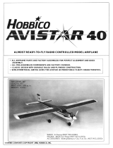
ALMOST READY-TO-FLY RADIO CONTROLLED MODEL AIRPLANE
• SUPERIOR QUALITY IN AN ALMOST-READY-TO-FLY MODEL.
• SPECIAL COVERING PROCESS YIELDS A STRONG, BRILLANT, AND FUEL-PROOF
FINISH.
• 80% COMPLETE OUT OF THE BOX - NO SANDING, PAINTING, OR FINISHING REQUIRED
• WORLD CLASS AEROBATIC CAPABILITIES, JUST LIKE THE REAL EXTRA 300.
• BEAUTIFUL SEMI SCALE APPERANCE.
WINGSPAN: 553/4"
LENGTH: 44 1/2"
WING AREA: 543sq.in.
WEIGHT: 91-95 oz.
RADIO: 4-Channel (Not Included)
ENGINE: .46 Performance 2-Cycle (Not Included)
or 60-70 4-Cycle (Not Included)
ACCESSORIES: Starting Battery w/Clip, Fuel Etc. (Not Included)
ENTIRE CONTENTS © 1990, V1.0 INC.

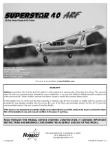
IMPORTANT: BEFORE YOU BEGIN.
Congratulations on your choice of an ASAP kit. BEFORE you begin assembly, carefully look through the box and
thoroughly read the instruction manual. Also check the parts list against the items in the box to be sure you have
everything that is on the parts list. Also check the parts list against the items in the box to be sure you have everything
that is on the parts list. Although we have taken great pains to simplify the building process, there are no shortcuts
to safety. These instructions are your guide to safe and successful flying.
Only after you are thoroughly familiar with the construction process should you proceed with assembly.
Remember! Under no circumstances will a dealer accept a kit back for return if assembly has already begun.
If the Extra 300 is not quite what you expected, return it to your dealer in New and Unused condition. However,
we think you will agree with us that the Extra 300 kit is one of the finest models of its type and will offer you many hours
of enjoyment.
BEFORE ASSEMBLY
CONSTRUCTION HINTS:
1. Trial fit each part before gluing. Be certain that the parts fit properly.
2. Use PlastiZap or a thin type Cyanoacrylate glue for installing the
plastic parts. Do not use too much, as it may run and spoil the
appearance. Do not get Cyanoacrylate on the foam parts of the Extra
300. Cyanoacrylate will destroy the foam.
3. It is best to use 30 minute epoxy where required. This allows time
to position the parts before the epoxy cures.
4. Before assembly, place your radio system on charge.
5. There is a metric ruler on page 3 to aid in finding the correct screw
sizes.
ADDITIONAL
ITEMS
The following items are needed for completing the Extra 300 kit:
Medium Fuel
Tubing
(12")...................................................................
1
.46 Sized 2-Cycle
Engine....................................................................
1
OR
.60
-
.70 Sized 4-Cycle
Engine............................................................
1
4-Channel Radio System
....................................................................
1
Pacer
PlastiZap CA Glue
....................................................................
1
Goldberg #481
Foam
Rubber
....................................................................1
Hobbico (HCAR3950) 30-Minute
Epoxy..............................................
1
Silicone
Sealer....................................................................................
1
Dubro
121
E-Z
Connects
(Optional)
....................................................2
Dubro
203 Kwik-Switch Mount
(Optional)............................................
1
Hobbico (HCAR3760)
Threadlock.......................................................
1
Dubro In
Line
Fuel
Filter......................................................................
1
TOOLS REQUIRED
TOOLS-
You will need the following tools to assemble the Extra 300: X-Acto knife,
Philips screwdriver (small and medium), needle nose pliers, drill, drill bits,
sand paper, ruler, and string.
2-
Most engines require a 1.5V glow plug starting battery, a glow plug clip,
and a quality brand fuel (consult the engine manufacturer's
recommendatiions).
A quality brand engine will be needed. We recommend the O.S. .46 SF
2-cycle engine or the O.S. 70 Surpass 4-cycle. A prop and fuel tubing will
be required for the engine.
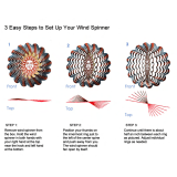
A four-channel radio control sytem with 4 servos is required for the Extra
300. The various components are pictured above.

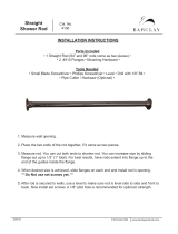
PARTS LIST
Before assembly, match the parts
in the exploded view of the Extra
300 with the parts in the kit. Check
off each part on the parts list. If any
parts are missing or damaged
return the kit to your hobby dealer.
Check to make sure that all the
listed parts are included in your kit.
1 Fuselage
2 Right Wing
3 Left Wing
4 Wing Center Cover (Plastic)
5 Vertical Fin
6 Rudder
7 Horizontal Stabilizer
8 Cowl (4 Piece)
9 Fuel Tank
10 NeopreneRing
11 Plastic Disc (Small)
12 Plastic Disc (Large)
13 Silicone Tubing
14 Clunk
15 3x18mm Self-Tapping Screw
16 Rubber Plug
17 Plastic Collar
Aileron Horn
Control Horns
Snap Clevis
Rod Clevis
Back Plates
18 Fuel Pipe
19 Mounting Plates (Angled)
20 Clevis Retaining Tube
21 Push Rod Exits
22 Stab. Root Cover (Plastic)
23 Wheels
24 Main Gear
25 Wheel Pants
26 Cock Pit
27 Canopy
28 Main Wing Joiners
29 Rear Wing Joiner
30 Front Wing Joiner
31 Rubber Shock Absorber
32 Cowl Brace
33 Aileron Servo Tray Mount
34 Aileron Servo Tray
35 8mm Dowel Rod
36 Wing Bolt Mounting Block
37 Balsa Tank Support
38 Wing Mounting Brace
39 3x12mm Self Tapping Screw
2 1/4" Spinner
Spinner Back Plate
40 Engine Mount
41 Mounting Plates
42 Shrink Tubing
43 Control Rod (Short-Bent)
44 Control Rods
45 Throttle Control Rod (Long)
46 Throttle Tube
47 Wood Push Rods
48 Plastic Disc (Red)
49 Main Servo Tray
50 Stabilizer Supports
51 Plastic Disc (Blue)
52 CockPit Mounts
53 Brass Sleeve
54 Brass Tube
55 Tail Wheel
56 Tail Gear
57 Tail Gear Mount
58 1/8" Wooden Wedge
59 0-Ring
60 Collars
61 Wheel Collar
62 4 x 40mm Screw
63 4 x 30mm Screw
64 2x15mm Screws
65 3 x 8mm Self-Tapping Screw
66 3 x 8mm Screw
67 3x12mm Self-Tapping Screw
68 3 x 5mm Screw
69 3.5 x 15mm Screw
70 3x12mm Screw
71 4x15mm Screw
72 4 x 20mm Screw
73 4mm Nut
74 2mm Nut
75
3mm Nut
76 4mm Washer
77 3mm Washer
78 2mm Washer
79 Lock Washers
80 4mm Washer
81 4mm Nylon Nut
82 Cowl Stripes (Red)
83 Decal Sheet
-3-

WING ASSEMBLY
A.
Right Wing
(Aileron
Installed) ..........1
B. Left Wing (Aileron Installed)......... 1
C. Main Wing
Joiner.........................
2
D. Rear Wing
Joiner.........................
1
E.
Front Wing
Joiner........................ 1
F Wing Center Cover (Plastic)........ 1
G. 8mm Dowel Rods
..........................2
H. Wing
Bolt
Mounting
Block.............
1
I. Wing Mounting Brace.................. 1
J.
4
x
30mm
Bolts
...........................2
K. 4mm Washer
...............................2
L
0-Ring
........................................2
M. Aileron Servo Tray
......................1
N. Aileron Servo Tray Mount............ 1
0.
Main
Swvo
Tray..........................
1
3. Remove the foam covering from the aileron servo mounting area
from the top side of the wing. Test fit the main wing joiner and the
rear wing joiner in the right and
left
wing
sections.
The dihedral angle
of the joiners should make the wing tips slightly higher than the
center.
4. Make sure that there is no gap between the wing halves. If there is,
sand the wing joiner ends until there is a tight fit.
1. Align and epoxy the two main wing joiners together. Hold tight until
the glue sets. You'll notice that there is dihedral angle cut into the
joiners so make sure they are perfectly lined up.
2. Check each wing half for smooth aileron operation. It is a good idea
to exercise (move back and forth) the ailerons to insure easy
deflection. Trim the end of the aileron if any rubbing is noticed.
-4-
5. Apply epoxy to one half of one side of both the main and rear wing
joiners and glue them to one wing half. Make absolutely sure the
wing joiner pocket is well coated with epoxy. Make sure the
dihedral angle is correct and that the wing halves are slid in all the
way. Clean any excess epoxy with paper towel and isopropyi
alcohol.

6. After the joiners have cured, apply epoxy where shown. The wing
roots, the wing joiners should be evenly and liberally covered with
epoxy. The wing joiner pocket should be heavily coated with epoxy.
9. Drill two 8mm (5/16") holes into the wing joiners for the dowel
rods. Drill through the front joiner and into the rear wing joiner.
7. Slide the two wing halves together slowly and wipe off any excess
glue. With the wing on a flat surface, hold one wing half down so the
other end will be elevated. The wing tip should be 1 1/16" off of
the surface. Hold the two wing halves firmly together with tape until
the epoxy has cured.
10. Epoxy the two dowel rods into the holes. Make sure they pass all the
way through the front joiner plate and are inserted into the rear
joiner.
8. Once cured, remove the tape. Position the front joiner as shown.
The flat edge of the joiner should line up with the top of the wing.
Next, remove and epoxy in that same position. Let cure. NOTE: You
may have to trim the covering for a tight wood to wood joint. This is
very important to the structural integrity of the wing.
11. Position the wing center cover on the bottom of the wing. Apply
Cyanoacrylate glue (PlastiZap) under the edges and hold until it
sets.
-5-

12. Epoxy in the main servo tray as shown.
15. Screw in the wing bolts into the wing bolt mounting block so that the
heads are 1/4" above the block. Apply ink or paint to the heads of
the two bolts.
13. Test fit the wing bolt mounting block to the inside of the fuselage. The
blind nuts should face down. Make sure that the blind nuts are
securly pressed in and then place a drop or two of Cyanoacrylate to
hold them in. Make sure that no glue gets on the threads
16. After the epoxy has cured, place the wing into the fuselage as shown.
Put the front in first by inserting the dowel rods in the holes. Once
in place lower the back into position. This will mark where you need
to
drill.
14.
Epoxy in the wing bolt mounting block. This is a high stress point and
extra care should be taken to ensure a strong joint. Let cure.
17. Place the wing mounting brace onto the wing as shown and center
the wing and brace in the fuselage. NOTE: The two indentations on
the brace should face up. Trim away any wood to allow the aileron
torque rods to move freely. Use PlastiZap to glue this in place.
-6-

LANDING GEAR INSTALLATION
18. Drill two 4mm holes 90' from the top wing surface for the wing bolts
where the paint marks are.
19. Assemble the wing bolts as shown (Bolt - Washer - Wing - 0-ring)
and temporarily fasten down the wing. Check for a good fit and
then remove.
20. Trial fit the aileron servo tray mount and tray to the wing. NOTE: The
front edge should be on the wood. You will have to trim away a little
covering to insure a good fit. You may also have to trim the bottom
of the servo tray mount so it will fit flush inside the wing. Epoxy the
aileron servo tray mount into the rear section of the wing servo mount
and then epoxy in the tray.
A. MainGear.................................. 1 H Wheel Pants...............................2
B.
Rubber
Shock
Absorber..............
1 I. 4mm
x
40mm Screw
...................2
C 4mm
x
30mm Screw
....................2
J.
3mm
x
12mm Screw
...................2
D. 4mm Washer.............................4 K.
3mm Washer.............................2
E. 4mm
Nut...
.................................6
L
3mm
Nut.
................................2
F. 4mm
Nylon
Nut............................
2
M.
Plastic
Spacer................................
2
G.
Wheel............................................ 2
1. Drill two 4mm holes at the indents.
2. Remove the wing. Place the two 4mm x 30mm screws with the
4mm washers into the two landing gear holes that are located inside
the front fuselage section.

3. Thread two 4mm nuts onto the two screws and tighten Next place
the rubber shock absorber over the screws.
6. Arrange the above parts as shown and then assemble together. Do
this
twice. Place
thread lock on the
threads when
installing
the
nuts
4. Now place the main gear over the screws and secure it with two 4mm
nylon nuts NOTE: tighten
the nuts
all
the way and then loosen them
both one turn. This will give the gear the correct shock absorbing
qualities.
7. Place the 3mm screw/washer into the top hole of the wheel pants
from the inside And then attach it to the top hole of the main gear
using a 3mm nut with threadlock.
5. Next, take the two wheel pants and drill two holes in each one The
first hole should be at the indent (4mm in diameter) The second
should be 3/8" above the first and smaller (3mm diameter) Apply
the wheel pant's decal stripes to both sides of the two wheel pants.
8. Flare open the pants and insert the wheel assembly Install the 4mm
nut with threadlock and tighten, holding the inside nut with needle
nose pliers.
-8-

9. Make sure that both wheels rotate freely. If they do not, trim away
the plastic as needed. Or if need be, loosen the nuts and reposition
the wheel.
2. Install the two mounting plates onto the engine mount. Next, paint
a strip on each plate using four 4mm x 15mm screws and washers
and proceed with the following step before the paint dries.
ENGINE INSTALLATION
FOLLOW THE SAME PROCEDURE FOR EITHER 2-CYCLE OR 4-
CYCLE INSTALLATION.
A.
Engine
Mount..............................................................................
1
B. 4mm
x
20mm
Screws
.................................................................4
C.
Mounting
Plates
..........................................................................
2
D. 4mm
x
15mm Screws
.................................................................4
E.
4mm
Washers.............................................................................
4
F.
Lock Washers
.............................................................................8
G.
3.5mm Screw
..............................................................................4
H. 3.5mm
Nuts
................................................................................4
3. Before touching the plates, align the engine so it is pointing straight
forward. Center the engine with the plates and carefully touch the
engine into position. Now carefully remove the engine and there
will be the guides for drilling the mounting holes.
1. Install the engine mount to the fuselage using four 4mm x 20mm
screws and four lock washers. Note the direction the mount is
installed for proper engine positioning. Also use threadlock on the
screw threads.
-9-
4. Drill two 4mm holes in each mounting plate at the marks.

5. Mount the plates to the engine using the 3.5mm screws up from the
bottom as shown. Next apply screw locking compound to the screw
threads and
tighten
on the 3.5mm nuts
with
lock washers.
Do
this
to both sides.
6. When mounting a four cycle engine, the existing throttle control
rod hole (for 2-cycle engines) will not work. Position the engine to the
mount and drill a 1/8" hole into the firewall so it will line up with the
throttle arm on the engine.
7. Now mount the engine to the fuselage. Use four 4mm x 15mm
screws with the four4mm washers. Be sure to use threadlock on the
screws.
ENGINE INSTALLATION
A.
Fuel
Tank................................................................................... 1
B. Clunk
..........................................................................................1
C.
Silicone
Tubing
....................................................................
..
...1
D.
Fuel
Pipe...........................................................
(2)
Long
(1)
Short
E. Plastic Disc(Large).....................................................................1
F. Plastic Disc(Small ......................................................................1
G. 3mm x 18mm Self-Tapping Screw ..............................................1
H. Rubber Plug ................ ......................................................... ....1
I. Neoprene Ring............................................................................1
J. Balsa Tank Support .................................................................... 1
1. Install one of the long and one of the short fuel pipes through the
rubber plug. Center the pipes in the cap. Place the two plastic discs
onto each side. The large one should be on the outside. The bump
on the small one should face the rubber cap Put the 3mm x 18mm
self-tapping screw in the center hole from the large end and tighten
it only a couple of turns into the small disc
10-
2. Attach the silicone tubing to the short fuel pipe and attach the clunk
to the other end

3. Carefully bend up the other fuel pipe so it will just touch the inside
top of the fuel tank.
6. Put a bead of silicone sealer on the neoprene ring.
4. Attach the complete fuel tank cap to the tank. Make sure that the
bent pipe is pointing to the top. Slide the cap on until the lip on the
fuel tank is in the groove of the cap. Then tighten the screw. Check
to make sure the clunk is free to swing at the bottom of the tank. This
is where the term "clunk" comes from.
7. Install the fuel tank from the inside of the fuselage with the fuel lines
facing front. Slide the tank into its mount and up into the hole in the
front of the fuselage. Make sure that the fuel tubing is through the
hole.
5. Glue the neoprene ring to the tank with silicone sealer. Attach two
pieces of fuel tubing (6" each) to the pipes. One is for the carburetor
the other is for the pressure tap on the muffler.
8. Epoxy the tank support to the inside of the front fuselage. Once
dry apply a bead of silicone sealer where the support and the
tank touch.
-11
-

RADIO INSTALLATION
A.
Aileron
Horn.................................
2
B.
Wood
Push
Rods.........................
2
C. Control
Rods................................
5
D. Control Rod (Short-Bent)............. 2
E.
ShrinkTubing.............................. 1
F. Throttle Control Rod (Long)......... 1
G. SnapClevis................................. 2
H.
Push
Rod Exits
...........................3
i.
Clevis Retaining Tubing
..............1
J.
Throttle
Tube...............................
1
3. Screw two snap clevises half way up the threads on the aileron
control rods. Next, cut two pieces of the clevis retaining tubing
(3/16") and slide them onto the rods.
1. Check the fit of your aileron servo in the aileron servo tray. You may
have to trim away some of the servo tray for a good fit. Install the
rubber grommets onto the servo case flange. Route the servo lead
through the hole in the bottom of the wing and fasten it to the aileron
servo mount using the screws provided with the radio system.
4. Attach the clevises to the aileron horns and slide on the retaining
tubes. After checking the neutral position of the aileron servo and
ailerons, put a mark on the push rods where the servo arm holes line
up. Be sure the aileron is in the neutral position.
2.
Screw the aileron horns onto the aileron control arms. Trim the wing
mounting brace as needed for full aileron movement. Make sure you
use the two horns with the larger holes.
5. At the mark, bend each push rod at a right angle. Next, cut the push
rods 6mm from the bend.
12-

RADIO INSTALLATION
6. Locate two rod clevises from the plastic parts tree.
9. Trial fit the servos into the fuselage servo tray, and trim the tray as
needed for a good fit.
7. Attach the rods to the servo arm using the rod clevis. NOTE: You
may have to use a different style servo horn for more throw as shown.
10. Install the three remaining servos (1/4" apart) into the tray using
grommet eyelets and screws. Be sure that the servos are
positioned correctly. Next, mount the radio switch. NOTE: Make
sure
that the
servo wires
all run
forward so they are easily
accessible.
8. Connect the aileron servo to the receiver and check the movement
of the ailerons. Make sure that both ailerons are neutral when the
servo is neutral. Adjust the clevises as needed.
11. We suggest installing an external switch mount so that the radio
system can easily be turned on and off from the outside without
taking the wing off. (The Dubro #203 Kwik-Switch Mount works
well.)
-13-

12. Assemble the rudder and elevator control rods using the parts
above.
15. Cut four equal pieces of the white shrink tubing (about 2" each)
13. Bend two of the long rods as shown for the elevator and one of the
rods for the rudder.
16. Assemble the elevator push rod as shown. Place the two elevator
rods into the double grooved end of one of the rods. Next, place one
of the short (pre-bent) rods into the other end.
14. Drill a 1/16" hole 2" from the ends (2 holes 1/16" apart on one end
of one rod) of both wood push rods. With a hobby knife, carefully
cut straight grooves from the holes to the ends. Only cut a groove
on one side of each end. except for one end of one rod (the one with
two holes). For this one end, make a groove on both sides.
17. Next, do the same with the other rudder rod. Make sure that each
rod fits in a groove. Now slide the four pieces of shrink tubing over
the ends of the wooden rods and shrink them with a heat gun or
lighter. To ensure durability, place a drop or two of Cyanoacrylate
glue to the edges.
-14

18. Punch out the three rod exits at the tail and insert the rudder pu sh rod
into the fuselage from the front and then through the bottom exit on
the right side. Do the same with the elevator rod, but put those
through the top two holes. It may be necessary to bend the rods
slightly to fit.
21. Use the throttle control rod and the white throttle tube for the engine
linkage. Lightly sand the plastic tube so the epoxy will adhere to it.
Cut the plastic tube so it is only 12" long.
19 Using PlasiZap, glue the three plastic push rod exits to the
fuselage.
22. Install the plastic tubing through the hole in the firewall to the servo
tray Epoxy the tube where it goes in If using a four cycle engine,
install the tube into the drilled hole from Page 10.
20 Check to make sure that the rods will easily move in and out with little
resistance. You may have to bend the rods slightly for a perfect fit
(we will connect the rods to the servos after the tail assembly).
23. Make a "Z" bend on one end of the throttle control rod and insert the
opposite end into the tube.
-15-

24. Connect the servos to the receiver and battery and center all radio
controls (including the throttle stick and move the servo horns so
they are in line with the servo as shown. After they are centered, pull
the throttle stick back down (low throttle). Install the straight servo
horns that are included with your radio system.
27. From the inside, pull back the throttle control rod so the carburetor
is closed. Now, mark the rod where it crosses the throttle servo horn
(in low posistion).
25. Connect the "Z" bend to the engine throttle arm. It may be necessary
to remove the arm from the engine for easier installation.
28. Next, at the marked point, make another "Z" bend, cutoff the excess
and attach it to the servo arm. For easy adjustments, an easy
connect can be used here. (Dubro#121 E-Z Connectors work well.)
26. Epoxy the white tube to the tube guide.
29. Check for proper radio operation of the throttle. Make sure that the
carburetor will move from low to high completely.
-16-

NOTE: The tail wheel parts M-T may vary due to an updated design.
See page 18, Step 10.
A.
Horizontal
Stabilizer..................... 1
L Tail Wheel................................... 1
M. Tail Gear..................................... 1
N. MetalStrip...................................1
0.
3mmx12mmSelf-TappingScrew 2
P.
3mm
x
5mm
Screw
.....................
1
Q. Wheel Collar
...............................1
R.
BrassCollar
................................1
B. Vertical
Fin...................................
1
C.
Rudder......................................... 1
D. 1/8-Wooden Wedge.................... 1
E.
Stab. Root Cover (Plastic)
...........
1
F. Stab. Supports.............................2
G. Plastic Disc
..................................4
H.
BrassSleeve
...............................2
I.
2mm
x
15mm Screw
....................2
J.
2mm Nut...................................... 2
K.
2mm
Washer
...............................4
3. Install the main wing. Next place the horizontal stabilizer onto the
tail. Hold it on and visually see if the wing and stabilizer are parallel.
If not, sand the higher side of the stabilizer mount until! the stabilizer
is parallel.
4. Next take a piece of string and attach it with a pin to the top center
of the fuselage. Make sure that the stabilizer is centered and stretch
the string to the corner of the elevator. Adjust the positioning of the
stabilizer so that both corners are the same length when moving the
string from side to side.
1. Test fit the 1/8" wooden wedge into the tail end of the fuselage. If
there is a good fit, epoxy it in place making sure that it is even with
the fuselage sides. NOTE: It may be necessary to trim away some
wood or glue to make the wedge fit flush.
5. Next, remove the stabilizer and apply epoxy to the wedge. Reinstall
the stabilizer and re-center like before.
-17-
2. Trim away as necessary part of the plastic rear cover to allow
proper fit of the horizontal stabilizer.

6.
Once the horizontal
stabilizer epoxy has cured,
trial
fit the
vertical fin
(without the rudder)
on
top
of
the horizontal
stabilizer
and
the
back
edge is even with the rear of the fuselage. Draw a line on both sides
of the fin as shown
9. When satisfied with the fairing positioning, apply cyanoacrylate glue
to the underside edge of the stabilizer cover and install in place
7 Next, apply epoxy to the top of the horizontal stabilizer and re
position the fin between the lines Make sure that the fin is still 90"
to the stabilizer Do the next step before the glue sets
10. Assemble the tail wheel section shown Slide on a brass collar,
the tail wheel, and install the wheel collar with a 3x5mm screw.
8. While the epoxy is still wet, position the plastic stabilizer fairing cover
over the fin Double check the positioning of the fin after doing this.
Allow epoxy to set.
11 Inserta 3mmx12mm self tapping screw through the middle hole of
the metal strip and attach to the under side of the tail section so
that the screw is positioned 1/2" from the end of the fuselage.
-18-

12. Now take the supports and bend the ends as shown above.
15. Install the tail wheel
assembly
through the
metal
strip.
Next,
trail
fit
the rudder onto the vertical fin. Notice where the bottom hinge
meets the fuselage and make a slot in the tail where the rudder hinge
needs to be with an X-Acto knife.
13. Attach the two supports onto the fuselage with a 3mm x 12mm self-
tapping screw. Make sure that the metal strip is straight.
16. Next, drill a 2mm hole about 1" deep at 7/8" from the bottom of the
rudder. The hole should be straight in from the front edge.
14.
Position
the
supports straightout (90')
to
the
fuselage.
Mark where
the supports touch the horizontal stabilizer, drill a 2mm hole on each
side at the marks. Next, cut 1/8" off of two brass sleeves. Finally,
attach the supports as shown in the drawing above.
17. Notch a small groove (1/8" deep) from the hole down to the bottom
for the tail control arm.
-19-

18. Place a small amount of epoxy on the hinges, in the groove, and on
the end of the tail control arm. (It is a good idea to place some
petroleum jelly onto the hinge center joint (point of movement) to
keep out any epoxy.
1. Glue (using PlastiZap) the rectangular mounting plates to the rudder
so that they are centered, one on each side, over the tail control arm
that is "inside" the rudder.
19. Carefully postion the tail control rod into the hole and the groove.
Wipe off any excess epoxy and then insert the hinges into the slots.
Wipe off any excess epoxy from the hinges and check for free
operation. Let cure.
2. Using PlastiZap again, glue the angled mounting plates, one on
each side, on the two elevator halves as shown.
ELEVATOR/RUDDER CONTROL ROD INSTALLATION
A.
Control
Horns..............................................................................3
B. Back
Plates....................................................................................3
C. Mounting Plates (Rectangled)
.....................................................2
D. Mounting Plates
(Angled)
............................................................4
E. Brass
Tubes................................................................................6
F. 2mm
x
20mm Screws
.................................................................6
G. Clevis Retainer Tube
..................................................................
1
H. Rod Clevis
..................................................................................2
I.
Snap
Clevis.................................................................................
3
3. Using the control horn as a guide, center and mark two holes for
drilling on all three mounting plates. The horns will then be
mounted - two underneath the elevator and one on the right side
of the rudder (as viewed from the rear).
-20-
/