Page is loading ...

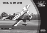
Wing Span .64-3/4 inches
Wing Area .712-1/4 inch2
Approx. Weight .4-3/4-5 1/2 lbs.
Engine Requirements .40-.46 2-cycle
.40-.50 4-cycle
• True UltraCote™ covering
• Positive self-righting flight characteristics
• 90% pre-built
• Extensive hardware kit included
• Break away motor mount prevents engine
damage during minor nose-overs
Specifications
Raising the Standard of Quality
in Almost-Ready-To-Fly Aircraft
ALMOST READY-TO-FLY
PRE-BUILT
90
%
9
HANGAR
TM
INSTRUCTION MANUAL

2
TICKET TO FLY
R/C Pilot Program
The Total Training Package
Congratulations on your selection of the Hangar 9 Easy Fly
40! Your kit comes complete with the “T
ICKET
TO F
LY R/C
Pilot Program,” a detailed video instruction guide designed
to help beginners become successful pilots.
This video guides you through every step of the learning
process — from building tricks and tips through your first solo flights. The
video shows in-depth procedures on radio setup, trimming the plane, and
breaking-in and tuning your engine. It covers the basic flight concepts you
need to know, like takeoffs, landings and, most importantly, how to find and
work with a qualified instructor. You’ll find out just what to expect when
you arrive at the flying field… before you even get there.
When you use the video in conjunction with the complete, photo-illustrated
instruction manual, you’ll gain the confidence and ability to successfully
meet the challenge of R/C flight. This video is an invaluable teaching aid
which will shorten the time it takes to properly learn to operate and fly the
Easy Fly 40.
Good Luck and Good Flying!
TM

3
Table Of Contents
Introduction 3
Contents Of Kit 4
Equipment Required 5
Tools And Supplies Required 5
Field Equipment Required 6
Optional Field Equipment 7
Section 1: Assembling The Wings 8
Section 2: Joining The Wing Halves 9
Section 3: Hinging The Rudder And Elevator 12
Section 4: Installing The Aileron Servo Trays 13
Section 5: Assembling The Fuselage 16
Section 6: Installing The Nose Gear 17
Section 7: Installing The Wing Dowels 18
Section 8: Assembling The Fuel Tank 19
Section 9: Installing The Fuel Tank 21
Section 10: Installing The Control Horns 22
Section 11: Installing The Horizontal & Vertical Stabilizers 24
Section 12: Installing The Engine 26
Section 13: Installing The Radio 29
Section 14: Installing The Linkages 32
Section 15: Setting Up The Radio 38
Section 16: Balancing The Model 39
Pre-Flight Check 40
Pre-Flight At The Field 41
Flight Instructions 42
AMA Safety Codes 43
Glossary 44

Introduction
Congratulations!
You are the proud owner of the highest quality almost-ready-to-fly (ARF) sport trainer available. The Easy Fly
40 is professionally built and pre-covered by craftsmen using genuine UltraCote
®
covering. The positive self-
righting flight characteristics and excellent slow-speed handling make the Easy Fly 40 one of the easiest-to-fly
airplanes available. Beyond its positive, gentle flight mannerisms, the Easy Fly 40 also offers outstanding
sport aerobatic capabilities. Loops, rolls, sustained inverted flight, and even outside maneuvers are all well
within its flight envelope.
In order for you to get the best performance and most enjoyment from your Easy Fly 40, it is important to
carefully read and follow this manual. If you’re a first-time flier, we strongly suggest that you seek qualified
help during your first flights. Your local hobby shop will be able to put you in touch with qualified pilots and a
local club.
Note: Due to temperature changes during shipping, the covering on your Easy Fly may be slightly wrinkled.
The careful use of a heat gun or iron is recommended to shrink the UltraCote
®
until its taut.
Warning
An R/C aircraft is not a toy! If misused, it can cause serious bodily harm and damage to property. Fly only in
open areas, preferably AMA (Academy of Model Aeronautics) approved flying sites, and have an experienced
modeler/pilot preflight your aircraft before its first flight and perform the aircraft’s first test flights. Please
follow all instructions included with your radio and engine. We cannot stress strongly enough the importance
of having an experienced pilot preflight your aircraft and be present during your first test flights!
4
The Easy Fly 40 is professionally built and
pre-covered by craftsmen using genuine UltraCote®
covering. UltraCote is completely reparable and can
be found at your local hobby shop.
ULTRACOTE
UltraCote is a registered trademark of Carl
Goldberg Models
®

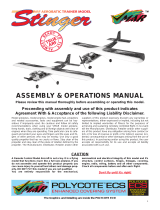
Contents Of Kit
5
A. Fuselage (#HAN1401)
B. Right wing half with aileron (#HAN1402)
C. Left wing half with aileron (#HAN1402)
D. Vertical stabilizer with rudder (#HAN1403)
E.
Horizontal stabilizer with elevator
(#HAN1404)
1. Pushrods
2. Aileron servo mounts (2)
3. Main landing gear
4. Nose landing gear
5. Spinner
6. Motor mounts and hardware
7. Wheels (3)
8. Fuel tank and hardware
9. Rubber bands (8)
10. Control horns
11. Wing joiner
A
B
C
E
D
1
11
9
8
7
6
5
4
3
2
10

R/C Radio System
4 Channels (minimum)
4 Standard Servos
Standard 450-650 mAh Battery
Recommended JR Systems
JR F400 FM
JR XP642
JR XP783
JR XP8103
R/C Engine
.40-.45 2-Cycle with Muffler
Recommended Thunder Tiger Engine
GP .42 with Muffler
R/C Aircraft Propeller
10-6 Prop with a .40-.46 Size Engine
6
Equipment Required
Adhesives
CA (cyanoacrylate) Glue (instant/thin and medium viscosity)
CA Remover (dissolve)
5-Minute Epoxy
30-Minute Epoxy
Tools
Clips (e.g. clothespins, binder clips)
Cloth
Drill and Assorted Drill Bits
Heat Gun
Heat Iron
Hobby Knife
Masking Tape
Needle Nose Pliers
Paper Towels
Pencil
#1 and #2 Phillips Screwdrivers
Rubbing Alcohol
Ruler (straight edge)
Sandpaper
Scissors
Straight Screwdriver
Thread Lock (e.g., Loc Tite Blue)
Toothpicks
90-Degree Triangle
Wax Paper
Z-Bender Pliers
Tools And Supplies Required

Field Equipment Required
HAN3000 – 2-cycle Performance Plug MDC101 Glow Driver Model Airplane Fuel
HAN 3005 – Extra Life Sport Plug
HAN104 12V Super Starter HAN102 12V Battery HAN118 Fuel Pump
HAN2510 Glow Plug Wrench
7

Optional Field Equipment
Extra Propellers Flight Box Power Panel
Prop Wrench Miscellaneous Tools Paper Towels
#64 Rubber Bands After Run Oil Extra Glow Plugs
8

❑ 1. Carefully remove the aileron from the right wing panel.
Note where the hinges and the aileron torque rod fit into
the aileron.
❑ 2. Mix a small amount of 30-minute epoxy, carefully
following the instructions included with the epoxy.
❑ 3. Using a toothpick, apply epoxy into the ailerons’ torque
rod hole. Fill the hole 1/2 full.
❑ 4. Replace the aileron on the right wing half. Make sure
the hinges slide in place and the aileron torque rod
inserts into its respective hole in the aileron. The gap
between aileron and wing should be a constant 1/16”.
❑ 5. Wipe off any excess epoxy using a paper towel and
rubbing alcohol.
❑ 6. Deflect the aileron and apply a small amount of thin CA
glue to each hinge. Make sure that the CA glue
penetrates into the aileron and wing while maintaining a
1/16” aileron gap.
❑ 7. Wipe off any excess CA glue using CA remover and a
paper towel.
❑ 8. Repeat this process for the left wing (Steps 1-7).
Note:
After the CA has dried completely, check to ensure that
the hinges are secure by pulling firmly on the ailerons.
Important:
The ailerons are fitted in place but not glued in. They
must be correctly glued prior to flying.
9
Left Wing Panel with Aileron and Hinges
Right Wing Panel with Aileron and Hinges
CA Remover
30-Minute Epoxy
Thin Instant CA Glue
Paper Towels
Rubbing Alcohol
Toothpicks
Section 1: Assembling The Wings
Parts Needed Tools Needed

❑ 1. Using a pencil, mark both wing roots (the exposed
wood end of the wing halves) as shown.
❑ 2. Using a hobby knife, carefully cut out the marked
section.
Important:
Do not cut into hard wood wing joiner section.
10
Aileron Servo Mounts (2)
Dihedral Brace
Left Wing Half from Section 1
Right Wing Half from Section 1
Standard Servo (1)
30-Minute Epoxy
Hobby Knife
Masking Tape
Paper Towels
Pencil
Rubbing Alcohol
Ruler
Wax Paper
Section 2: Joining The Wing Halves
Parts Needed Tools Needed

❑ 3. Locate the dihedral brace (also called the wing joiner).
Using a ruler and pencil, mark the exact center of the
brace as shown.
❑ 4. Mix approximately 2 ounces of 30-minute epoxy. In
this step, be sure to use plenty of epoxy. Using a scrap
piece of wood, smear the epoxy into the wing joiner
cavity of both wings. (Remember, use plenty of epoxy.)
❑ 5. Coat one half of the dihedral brace with epoxy up to the
line. Note the orientation of the V of the dihedral
brace. Install the epoxy-coated side of the dihedral
brace into a wing half up to the line, making sure the V
of the dihedral brace is positioned correctly as shown.
11
Section 2: Joining The Wing Halves
CONTINUED

❑ 6. Apply epoxy to the exposed area (other end) of the
dihedral brace. Uniformly coat both wing roots with
30-minute epoxy.
❑ 7. Carefully slide the two wing halves together. Firmly
press the two halves together, allowing the excess
epoxy to run out. Using rubbing alcohol and a paper
towel, clean off the excess epoxy.
Important:
Be sure the wings are pressed firmly together at the
center section. Be sure that the leading and trailing
edges line up properly. Use masking tape as necessary
to hold the wing halves in position.
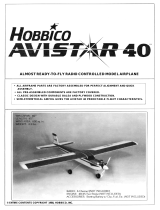
❑ 8. Place a 12” x 12” sheet of wax paper on the edge of a
flat table. Place the center section of the wing on the
wax paper with the aileron torque rod hanging off the
edge of the table. Prop up each wing tip 2-1/2 inches
off the table as shown. Books work well for this.
❑ 9. Wipe off any excess epoxy using rubbing alcohol and
paper towels. Allow the wing to set undisturbed
overnight to dry completely.
12
Section 2: Joining The Wing Halves
CONTINUED

13
Horizontal Stabilizer with Elevator and Hinges
Vertical Stabilizer with Rudder and Hinges
CA Remover
Paper Towels
Thin Instant CA Glue
Section 3: Hinging The Rudder And Elevator
Parts Needed Tools Needed
❑
1. Push the elevator and horizontal stabilizer together until
there is a constant 1/16” gap between the two and the
edges are lined up correctly.
❑ 2. Deflect the elevator and apply thin CA glue at the
hinges so that it absorbs both into the stabilizer and the
elevator (4 places).
❑ 3. Using the same technique, hinge the rudder to the
vertical stabilizer.
❑ 4. Wipe off any excess CA using CA remover and a paper
towel. Set these assemblies aside for now.
Note: After CA has dried completely, check to ensure that the
hinges are secured by pulling firmly on the control
surfaces.

14
❑ 1. Mix a small amount of 5-minute epoxy as per the
instructions included with the epoxy. Remember, once
this epoxy is mixed, you have only 5 minutes of
working time until it dries.
❑ 2. Spread a thin layer of epoxy over the entire surface of
one side of an aileron tray.
❑ 3. Join the two aileron trays as shown and clamp them
together using four clips. Be sure the two trays are
properly aligned. Wipe off any excess epoxy with a
paper towel and set aside to dry for 15 minutes.
❑ 4. Using a ruler, measure the distance on the bottom of
the wing at the center line 5-1/2 inches from the trailing
edge and mark with a pencil.
❑ 5. Next, measure 3-3/4 inches from the leading edge back
to the center line and mark with a pencil.
Aileron Servo Trays (2)
Wing Center Section Tape
Clips (e.g., clothespins,
binder clips) (4)
5-Minute Epoxy
Hobby Knife
Masking Tape
Paper Towels
Pencil
Ruler
Section 4: Installing The Aileron Servo Trays
Parts Needed Tools Needed

15
❑ 6. Unclamp the aileron tray when dry and position it on
the center line so the two marks are visible on the
inside of the aileron tray.
❑ 7. Carefully trace around the outside of the aileron tray
using a pencil.
❑ 8. Remove the aileron tray. Using a sharp hobby knife,
carefully cut through the plastic covering. Be careful
not to cut into the wood on the line you just made in
Step 7.
❑ 9. Carefully remove the covering in the aileron tray area.
This is necessary so that the tray will properly adhere to
the wing.
❑ 10. Mix a small amount of 5-minute epoxy and spread it
over the entire area of one side of the servo tray.
S
ection
4: Installing The Aileron Servo Trays
CONTINUED

16
❑ 11. Place the aileron tray, glue side down, on the exposed
wood area on the bottom of the wing and gently press it
into position. Use masking tape if necessary to hold in
position until dry. Allow 15 minutes for the epoxy to
cure.
❑ 12. Using a sharp hobby knife, carefully cut out the balsa
wood from the inside section of the aileron tray and
remove.
❑ 13. Locate the wing center tape (white adhesive-backed
tape) and remove the adhesive backing. Starting at the
edge of the aileron tray, apply the tape around the wing
at the center section, ending at the other side of the
tray. Use a hobby knife to trim the excess length of
tape. Your wing is now complete.
❑ 14. Locate the small blue decal (square in shape) on the
decal sheet included with your kit. Apply this decal to
the leading edge of the wing to cover the wing center
tape that you have just applied. Press firmly to ensure
that the decal adheres properly to the wing.
S
ection
4: Installing The Aileron Servo Trays
CONTINUED

17
❑ 1. Locate the main landing gear slot in the bottom of the
fuselage. Position the two landing gear straps across
the slot as shown and drill four 1/16” holes using the
straps as a guide. Remove the straps after all four holes
are drilled.
❑ 2. Locate the two main landing gear struts and insert them
into the landing gear slot as shown. Make sure the ends
fit into the holes in the edges of the slot.
❑ 3. Reposition the landing gear straps over the 1/16” hole
you drilled in Step 1. Screw into position with the four
sheet metal screws provided.
❑ 4. Place the wheels on the ends of the struts and secure
them with the supplied wheel collars. Use thread lock
on the collar screws.
Fuselage
Main Landing Gear (2 pcs)
Main Landing Gear Hardware
Wheels (2 pcs)
Wheel Collars with Screws (2 pcs)
Drill with 1/16” Drill Bit
#1 and #2 Phillips Screwdrivers
Thread Lock
Section 5: Assembling The Fuselage
Parts Needed Tools Needed

18
❑ 1. The nose gear mount is pre-assembled onto the front
firewall of the fuselage. Locate the nose gear. On the
straight end, first slide the steering arm onto the nose
gear (note the orientation as shown in the photo). Use
thread lock and a #2 Phillips screwdriver to secure the
steering arm in place. Next, install a collar and secure it
in place with the thread lock and a machine screw. Now
slide the spring into position.
❑ 2. Insert the nose gear assembly from Step 1 into the nose
gear mount (attached to the front of the fuselage). Be
sure the spring stays in position and rests against the
nose gear mount. Install the collar on the top end of the
landing gear flush with the landing gear, and secure it
into position with a screw and the thread lock.
❑ 3. Attach the nose wheel and hold it in place using a
wheel collar and screw.
Nose Gear Wheel (1)
Spring Wheel Collar with Screws (2)
Steering Arm
#2 Phillips Screwdriver
Thread Lock
Section 6: Installing The Nose Gear
Parts Needed Tools Needed

19
❑ 1. Using a sharp hobby knife, carefully cut the covering
around the four holes as shown, leaving a circle that the
dowel will be pressed into.
❑ 2. Install the two dowels and position them so that an
equal amount of dowel extends from each side of the
fuselage. Using thin CA glue, apply five drops around
each side of the wing dowel (4 places) where the dowel
touches the fuselage.
❑ 3. If necessary, use a paper towel and CA remover to wipe
off any excess CA glue.
Fuselage
Wing Dowels (2)
CA Remover
Hobby Knife
Paper Towel
Thin Instant CA Glue
Section 7: Installing The Wing Dowels
Parts Needed Tools Needed

20
Clunk (brass fuel pickup)
Copper Tube, Long (vent)
Copper Tube, Short (pickup)
Fuel Line, Small
Fuel Tank
Plastic Cups (2)
Rubber Stopper
3mm Screw and 3mm Nut
Hobby Knife
#1 Phillips Screwdriver
Section 8: Assembling The Fuel Tank
Parts Needed Tools Needed
❑
1. Locate the black rubber stopper. Insert the short copper
tube into one of the open holes in the stopper so that an
equal amount of tube extends from each side. This tube
will be the fuel tank pickup tube.
❑ 2. Locate the long copper tube and bend it using your
fingers, as shown. This tube will be the fuel tank vent
tube.
❑ 3. Slide this tube into the other open hole of the stopper,
as shown.
❑ 4. Slide the two white plastic caps over the copper tubes
as shown. Note the orientation of the caps. The small
inside cap and the three “pegs” face away from the
black rubber stopper. The large outside cap and the
“raised center” go away from the black rubber stopper.
/