Page is loading ...

Sturdy
Birdy
INSTRUCTION BOOK
WARNING! THIS IS NOT A TOY!
Assembly and operation of this aircraft must be done by or under the direct
supervision of a responsible adult. If not handled correctly, this model is capable of
inflicting serious bodily harm. It is your responsibility and yours alone to assemble this
model correctly, properly install all R/C components, and to test and operate it in a safe
and responsible manner.
Copyright
1994

Table of Contents
Introduction............................................................................................................2
Parts List...............................................................................................................3
Additional Item Description................................................................................4
Additional Item List.............................................................................................4
Tools or Supplies Needed.....................................................................................5
Fin/Rudder Construction....................................................................................5
Stabilizer / Elevator Construction ........................................................................7
Wing Assembly ....................................................................................................8
Covering..................................................................................................................9
Installing the Hinges ............................................................................................9
Attaching the Control Horns ..............................................................................10
Fuselage Construction........................................................................................10
Final Assembly...................................................................................................16
Balancing..............................................................................................................
17
Getting Ready for Flying ...................................................................................17
Flying .................................................................................................................17
Repairing.............................................................................................................18
INTRODUCTION
Congratulations on your purchase of the HOBBICO STURDY BIRDY, THE FIRST REAL SUPER TRAINER You
now own the BEST FLYING durable trainer available By following these instructions as you assemble the model you
will have a great flying plane that will not only teach you how to fly but it will stick with you while you learn, no matter
how long it may take!
The first thing you should do after reading this paragraph is check the parts in this kit against the parts list on the next
page to make sure everything is here
We strongly recommend that you join AMA, The Academy of Model Aeronautics Being an AMA member entitles you
to liability insurance, puts you in touch with your local flying club and includes a subscription to MODEL AVIATION
magazine which has a monthly listing of all "goings on" in model aviation
The insurance is the most important advantage of the AMA membership because if your model hits someone or
something you are liable for any damage it causes.
The address for the AMA is.
Academy of Model Aeronautics
5151 East Memorial Drive
Muncie, IN 47302
(800) 435-9262
We also recommend that you join your local flying club There you will find people who can help you learn to fly and
teach you the safe ways of handling your aircraft.
2

PARTS LIST
Stock # ..........Description ................................Qty
ARF1F01 ......Plastic Fuse Tube..........................1
ARF1F02 ......Aluminum Channel ......................1
ARF1P01 ......Instruction Book...........................1
ARF1R05...... 1/64" Ply Fin Doubler..................1
EM2040 ........Engine Mount (Left & Right).......1
ARF 1W02.....Plastic Wing Protector..................1
FWING01L... Molded Foam Wing - Left............1
FWING01R...Molded Foam Wing - Right..........1
L-6U..............Aluminum Landing Gear..............1
PLTB009 .......24" Inner Pushrod........................2
PLTB011 .......24" Outer Tube .............................2
PLTB012....... 12" Inner Pushrod.........................1
PLTB013....... 12" Outer Tube.............................1
NYLON87 ....CA Hinge Strip .............................1
ARF1A01 .....Stab & Wing Sub-Pack
ARF1R04......Balsa Fin Doubler.........................1
ARF1S01 ......Stab Front .....................................1
ARF1S02 ......Stabilizer.......................................1
ARF1S03 ......Elevator.........................................1
ARF1W01 .....Birch Wing Joiner..........................1
ARF1A02 .....Fin & Rudder Sub-Pack
ARF1R01 ......Fin Front.......................................1
ARF1R02......Shaped Fin....................................1
ARF1R03 ......Rudder .........................................1
ARF1A03 .....Small Wood Parts Sub-Pack
ARF1F03 ......Firewall Doubler...........................1
ARF1F04 ......Firewall ........................................1
Stock #..........Description ................................Qty
ARF1F05 ......Landing Gear Strips.....................2
ARF1S04 ......1/16" Ply Stab Doubler.................1
DOWEL030.. 1/4" Dowel....................................4
ARF1M01 ....Hardware Sub-Pack
NUTS001 ......4-40 Blind Nut..............................6
NUTS002......4-40 Hex Nut................................2
NUTS010......6-32 Hex Nut................................4
NUTS014......8-32 Hex Nut................................2
NYLON03 ....Control Horn.................................2
NYLON17 ....Nylon Clevis.................................3
NYLON52 ....5-1/2" Nylon Tie...........................2
SCRW002 .....2-56 x 5/8" Bolt............................4
SCRW010 .....#4 x 5/8" Sheet Metal Screw .......4
SCRW024 .....#2 x 3/8" Sheet Metal Screw........8
SCRW055 .....6-32 x 1-1/2" Bolt.........................2
SCRW052 .....4-40 x 5/8" Bolt............................4
SCRW053 .....8-32 x 1/2" Bolt............................2
SCRW104 .....4-40 x 1-1/4" Bolt.........................4
WBNT146.....Pre-bentTailskid...........................1
WIRES16......12" Threaded Link Rod................3
WIRES20......1" Threaded Link Rod..................3
WSHR002.....#4LockWasher............................2
WSHR004.....#6 Flat Washer...............................
WSHR005.....#4 Flat Washer..............................4
WSHR010.....#8 Lock Washer............................2
WSHR011.....#8 Flat Washer..............................1
3

ADDITIONAL ITEMS
NEEDED
Here is a description of some of the additional items
you will need to assemble your STURDY BIRDY.
GLUES
C/A (Cyanoacrylate) glues will be used to glue the
wood parts together because they are strong and very
fast curing Do not use C/A glues for any of the wing
construction because most C/A glues will attack and
dissolve the foam wing They come in different
viscosities Thin C/A glue can be used when gluing parts
with a good tight joint When using this type of C/A,
assemble the parts first and then add the glue It will
penetrate the joint and cure in a couple of seconds Thick
C/A glue has a longer curing time that gives you more
time to get the parts assembled accurately before the
glue cures and the thicker consistency helps fill poor
fitting joints C/A Accelerator spray can be very handy
for speeding up the curing process of the thick C/As.
Epoxy is a two part adhesive that has to be mixed
before it will cure We will use epoxy glue for the wing
assembly since it takes a little longer to cure and does
not attack foam Epoxies come in several different types
with many different curing times We recommend Great
Planes Pro 30 Minute Epoxy (#GPMR6047).
ENGINE
The STURDY BIRDY is designed to fly with a
standard 20 size 2-cycle engine The OS 20 FP is a
great, inexpensive engine that provides plenty of power.
This combination is ideal for the average beginner. A
25- 30 size engine can be used if you would like
snappier performance especially at higher elevations
where the air is thinner We recommend that you do not
use an engine larger than a 30 as the additional weight
makes the plane more difficult to fly at slow speeds The
Great Planes adjustable engine mount provided with the
STURDY BIRDY will fit most .20-.30 engines.
RADIO
The STURDY BIRDY requires 3 channels to fly but
there are not many 3 channel radios produced anymore
Therefore you will more than likely end up purchasing a
4 channel radio with 3 or 4 servos which usually costs
less than the three channel radios anyway Your next
plane may require four channels since it will probably
have ailerons The radio system you purchase should
have standard size servos so they will fit into the
fuselage channel Mini or micro servos will also work
but they will require some modifications to fit properly.
Large servos will not work in the STURDY BIRDY.
FUEL TANK
The STURDY BIRDY was designed to hold a square
tank We recommend a Great Planes 6 oz. tank
(#GPMQ4102).
COVERING
Although not absolutely necessary, the "tail
feathers" and the wing should both be covered with a
"low heat" type iron-on covering Top Flite Econokote
is perfect for your STURDY BIRDY. The covering
will not only make your plane look nicer, but it will
also add strength and make it last longer.
HERE IS A HANDY LIST OF THE
ADDITIONAL ITEMS YOU WILL NEED.
1 .20 - .30 2-Stroke Engine
1 3-4 Channel Radio with Standard Servos
2 or 3 9x4 or 9x6 Propellers
2 2-1/2" Wheels (Great Planes #GPMQ4223)
1 6 oz Tank (Great Planes #GPMQ4102)
1 box #64 Rubber Bands (Hobbico #HCAQ2020)
1/2 oz. Thin CA (Great Planes #GPMR6001)
1/2 oz. Thick CA- (Great Planes #GPMR6013)
1 30 Mm. Epoxy (Great Planes #GPMR6047)
1 roll Low Heat Iron-on Covering
(Top Elite Econokote)
1 1/4" Foam Rubber (Hobbico #HCAQ 1000)
1 12" Medium Fuel Tubing
(Great Planes #GPMQ4131)
TOOLS NEEDED FOR ASSEMBLY
Hand or Electric Drill
Drill Bits (3/32", 1/8": 3/16": 5/32", 7/32")
Sanding Block or T-Bar Sander
Sealing Iron
Razor Saw
Hobby Knife
Pliers
Screwdrivers
T-Pins
Hammer
Waxed Paper
Nylon Reinforced Strapping Tape
4

CONSTRUCTION
FIN/RUDDER
D 1. The fin is made up of the three pieces shown above.
Locate these three pieces and lay them out.
D 2. Glue the front part of the fin to the main part using
thin C/A. Assemble the two parts and check to make
sure they fit properly and then apply a line of C/A along
the joint. When the glue has cured, flip the pieces over
and add a little glue to the other side.
so that the outer hinges are approximately 1" from the
ends of the rudder and the middle hinge is in the center.
D 4. Draw a line down the middle of the trailing edge of
the fin and also down the middle of the leading edge of
the rudder. A sheet of wood (or anything) 1/8" thick laid
down next to the piece makes it easy to do this. Transfer
the hinge locating marks from the side to the edges as
shown above.
D 5. Use your hobby knife with a #11 blade to cut the
hinge slots in both the fin and the rudder. The slots
should go straight into the balsa without coming out the
side and should be about 3/4" deep.
CAUTION!!!: You must use extreme care when
cutting hinge slots with an Xacto knife, to avoid
cutting yourself! If the balsa part breaks while you
are pushing on the knife, the blade could go into your
hand before you know it! A good precaution is to
wear leather gloves while performing this step.
D 3. Lay the rudder in place against the trailing edge of
the fin and, using a hinge (see step 29, p. 9) as a
template, mark the hinge locations. They are spaced out
5

D 6. Trial fit the fin and rudder together using the hinges
to check for proper alignment. Do not glue the hinges in
place yet! Sand the rudder and/or fin so they match each
other at the top.
D 7. Remove the hinges from the rudder
and bevel the leading edge with your
sanding block as shown in the sketch. This
is to allow the rudder to swing either
direction once the hinges are glued in.
D 8. Add the 1/4" x 1/2" balsa doubler to each side of
the fin as shown in the photo above. Use a razor saw to
cut the excess off at the leading and trailing edges.
D 9. Check the fit of the fin assembly into the aluminum
channel. It will most likely be a little loose and we want
a nice tight fit. Add a strip of the 1/64" plywood doubler
to ONE side of the fin gluing it to the balsa doubler.
Check the fit again and if it is still a little loose, add a
plywood doubler to the other side. If you need to you can
sand the plywood slightly to help the assembly fit. Also,
you can have the covering material continue down over
the doublers if you need the additional thickness.
D 10. Position the fin assembly in the channel with the
trailing edge of the fin even with the end of the channel
and press it in place. Mark the location of the stabilizer
bolt holes on the bottom of the fin and then remove the
fin from the channel.
D 11. Wrap a piece of masking tape around a 7/32" drill
bit about 1/2" from the end of the bit.
D 12. Drill two holes in the bottom of the fin assembly
to make a space for the stabilizer bolts. Be careful not to
drill any deeper than the masking tape or you may punch
through the side of the fin.
6

D 13. Use a sanding block to round the edges of the
fin/rudder assembly as shown above. Give the sides a
quick sanding with some fine sandpaper to get it ready
for the covering. This completes the basic assembly of
the fin and rudder. The hinges and control horn will be
installed after everything is covered.
D 16. Mark the hinge locations using the same technique
you used in step #4. There are five hinges used here. The
outer hinges are approximately 1" from the edge. The
middle hinge is in the center and the other two hinges are
centered between the outer hinges and the middle hinge.
These hinge locations are not critical but proper
placement makes it easier to find the slots after the parts
are covered. Cut the slots for the hinges and test fit the
stabilizer and the elevator together to check for proper
alignment between the two parts.
STABILIZER
D 14. The stabilizer and elevator are assembled from
these three main pieces. Locate these and let's get started.
D 15. Glue the front of the stabilizer to the back using
thin C/A just as you did for the fin in step #2.
D 17. Use some thick C/A to glue the 1/16" plywood
doubler in place on the stabilizer. This side is now the
bottom of the stabilizer. Use a ruler to get this piece
centered as close as possible. Use a drafting triangle or
carpenter's square to draw a line perpendicular to the
stabilizer trailing edge and through the center of the
stabilizer to the point where the leading edges meet.
D 18. Use a pencil and a rubber band to hold the
stabilizer in place as shown in the photo. Sight down the

bottom of the channel and line the stabilizer up with the
channel (using the line you just drew) When you are
satisfied with the alignment draw a line down both sides
of the channel on the top of the stabilizer.
D 19. Remove the pencil and rubber band and with the
stabilizer centered over the lines, drill two 1/8" holes
through the stabilizer using the holes in the channel as a
guide The trailing edge of the stabilizer should be
slightly past the end of the channel.
D 20. Use a sanding block with some fine sandpaper to
round off the leading edges, trailing edge and the tips as
you did tor the fin and rudder Also sand the top and
bottom surfaces smooth This completes the basic
assembly of the stabilizer and elevator The control horn
and the hinges will be installed after the tail is covered
slots in the wing to make sure it fits nicely Mix up
about 1/2 oz of epoxy and spread it throughout the
slot in one wing panel With the wing panel upside
down, insert the joiner in place and squeeze out all the
excess epoxy so that the joiner is flush with the bottom
of the wing (which is facing up) Try to use enough
epoxy so that the slot is completely full and level with
the surfaces of the wing
D 23. Lay some waxed paper down on the work surface
and mix up another ounce or so of epoxy Spread the
epoxy throughout the slot and on the root (middle end)
of the other wing panel Slide the two wing panels
together and line them up as close as possible Use
several T-pins and masking tape to help hold them in
alignment Flip the wing assembly over so that the
bottom of the wings are facing up and make sure that the
joiner is seated properly in the slot Wipe oft any excess
epoxy before it starts to cure It is important that the
wings are joined with both panels being accurately
aligned with each other.
WING ASSEMBLY
D 21. Using a sanding block with some fine grit
sandpaper, (240-320 grit) remove the little nubs and any
mold lines left on the wing from the molding process.
D 22. Test fit the 1/8" plywood dihedral joiner in the
D 24. After the epoxy from the last step has fully cured,
place the wing upside down on the edge of a table so that
only 1/2 of the wing (from one wing tip to the center
joint) is resting on the table Starting at the wing tip that
is resting on the table, lay a strip of nylon reinforced
strapping tape down so that it crosses over the center
joint
directly
over
the
wing
joiner
Press
the
tape
firmly
onto the wing and down into the fillet (where the bottom
of the wing meets the mounting platform) and then flip
the wing around and continue the strip of tape out to the
8

other wing tip. Apply two more strips of tape between
this strip and the trailing edge of the wing and the fourth
strip should be added between the first strip and the
leading edge of the wing The photo shows where the
strips should be located. Try to get this tape stuck down
as tightly as possible because it adds a tremendous
amount of strength to the wing when properly applied.
Make sure you do not change the washout (twist) or
dihedral of the wing when applying the tape strips If
you are planning on doing some aerobatics or combat
with your STURDY BIRDY you should also put three
strips of tape on the top surface of the wing.
INSTALLING THE HINGES
D 28. After covering the tail surfaces, the hinges can be
installed Use your hobby knife to find the slots you cut
earlier and make slits in the covering so you can push the
hinges into place and trial fit the pieces together again.
D 29. Cut the supplied 2" x 9" CA Hinge Strip into 24
individual 3/4" x 1" hinges and bevel the corners as
shown in the sketch Install the control surfaces with the
hinges centered in place Make sure the surface operates
smoothly Deflect the surface all the way in one
direction, then apply several drops of thin CA onto the
center of each hinge The CA will wick throughout the
entire hinge joint and into the wood Deflect the surface
the other direction and glue the same way. Flex the
surface to loosen it up.
D 25. Trim the plastic center section protector to size by
using either scissors or your hobby knife to cut along the
scribe lines Use some coarse grit sandpaper to scratch
up the inner surface of the protector so the glue will
adhere better Test fit it on the wing and then use epoxy
to glue it in place.
COVERING
D 26. The tail surfaces (fin, rudder, stabilizer and
elevator) should be covered with one of the iron-on
coverings to help protect them from becoming fuel
soaked and ruined If you are also going to cover the
wing, which will help it look nicer longer (and add a
small amount of strength), you can save a little money
by only buying one roll of low temperature covering
(Top Flite Econokote is recommended) and using it for
both the wing and the tail surfaces Otherwise you can
use any type of covering for the tail surfaces, but,
remember to use a low heat covering for the wing A
few stripes or your AMA number can really add to the
looks of your STURDY BIRDY.
D 27. Follow the instructions that come with the
covering and cover the tail surfaces at this time It is a
good idea to cover the bottom surfaces first to get
familiar with the covering since these surfaces will
normally not be seen When covering the wing, cover
right over the tape and plastic wing protector, just try
to use as little heat as possible.
ATTACHING CONTROL HORNS
D 30. Position the nylon control horn on the left side of
the rudder about 1" up from the bottom with the four
holes lined up with the leading edge. Use a drop of Thin
C/A to tack glue the horn in place.
9

D 31. Drill two 3/32" holes through the rudder using the
control horn as a guide.
round off the corners with a
sanding block. Test fit the doubler
into the front of the plastic
fuselage tube as shown in the
photo. The firewall doubler
should fit into the fuselage with a
snug but not tight fit. The front of
the fuselage is cut at a slight angle
so the firewall and thus the engine
will point down slightly. Because
of this angle the top and bottom
edges of the firewall doubler are
also cut at a slight angle. Make
sure you install the firewall
doubler so all of its sides match
up nicely with the sides of the
fuselage as shown in the sketch.
D 32. Secure the horn to the rudder with two 2-56 x
5/8" machine screws. The screws should thread into
the nylon "nutplate" on the opposite side of the rudder.
Although not necessary, you may use some wire
cutters or an abrasive cutoff wheel to cut the screws
off even with the plate.
D 33. The other control horn should be installed on the
top surface of the elevator about 1" to the right of the
centerline. Follow the same procedure for installing
this control horn.
FUSELAGE
D 35. The 3/8" plywood firewall doubler is now glued to
the 1/4" plywood firewall front. Use either Thick C/A or
epoxy and make sure that the front of the firewall
doubler is centered on the back of the firewall. Wipe
away all excess glue that squeezes out.
D 36. Draw a vertical and horizontal centerline on the
1/4" plywood firewall. Cut the engine mount template
from the back of this booklet and tack glue it to the
firewall, aligned with the centerlines. Drill a 1/8" bolt
hole at each of the marked locations.
D 34. Locate the 3/8" plywood firewall doubler and
10

D 37. Cut the "spreader bar" off each mount half. Trim
off any burrs or flashing, then snap the mount halves
together. Bolt the mount to the firewall with four 4-40 x
1" screws and 4-40 blind nuts. Tightening the screws
will draw the blind nuts into position.
D 40. Temporarily install the engine on the mount with
two #4 x 1/2" sheet metal screws. Mark the location of
the throttle pushrod. Remove the engine and drill a
3/16" hole for the outer pushrod tube.
D 41. Secure the engine to the mount with four #4 x
1/2" sheet metal screws.
D 38. Test fit your engine to the mount. Adjust the
width of the rails to fit the engine. Tighten the mounting
screws securely. Apply a couple of strips of masking
tape to the rails, position the engine, then mark the
engine's mounting holes onto the rails (masking tape)
with a pen or pencil.
D 39. Remove the engine and drill the rails where marked
with a 3/32" drill bit. Try to keep the holes straight and
vertical. You may use #4 \ 1/2" sheet metal screws to
mount the engine, or tap the holes with a 4-40 tap.
D 42. Use a small piece of coarse sandpaper to scuff up
the inner floor of the aluminum channel in the area
around the front 11/64" bolt hole.
11

D 43. Insert one of the 8-32 x 1/2" machine screws into
the hole so that it sticks out the bottom of the channel
and glue it in place with plenty of thick C/A or epoxy.
This screw will be covered by the battery pack
prohibiting a screwdriver from being used to keep it
from turning, so glue it securely but be very careful not
to get any glue on the threads.
D 44. Use some nylon reinforced strapping tape to
securely hold the battery pack on the front end of the
channel. Square battery packs fit very nicely but most
flat packs will also fit, just tape them flat onto the
channel. The battery should protrude approximately 1/8"
past the end of the channel to keep the fuel tank from
rubbing against the end of the channel.
D 45. The servos are "press fit" into the aluminum
channel and then held in place with nylon strapping tape.
Standard size servos should fit very nicely and smaller
servos can be held in place by using a piece of wood to
fill the space between the
servo sides and the
channel. Large servos
will not work in the
STURDY BIRDY. The
servos should be placed as
far forward in the channel
as possible and right next
to each other, but do not
overlap the servo
mounting lugs. the front
two servos should be
mounted with their servo output shafts towards the back
of the plane and the back servo should have its output
shaft towards the front of the plane. The servo wires
should be routed out to the side of the servo without
going under any servos. Wrap two layers of nylon
strapping tape all the way around each servo and the
aluminum channel to hold it in place. Hook up the entire
radio system and turn it on (see the instructions included
with your radio). Adjust the transmitter trims so they are
in the middle of their slots. Remove the screws that hold
the servo horns in place and adjust the horns so that they
are perpendicular to the servo. This will be their neutral
position. It is a good idea to use single arm servo horns
rather than the round horns most servos come with. The
sketch shows how to cut a horn for use here. Replace the
screws that hold the horns in place. (See the photo at
step 49).
D 46. Attach the stabilizer/elevator
to the back of the channel using
two 4-40 x 5/8" machine screws,
two #4 flat washers, two 4-40 lock
washers, and two 4-40 nuts. The
sketch shows how the pieces are
installed. The pre-bent tail skid is
held in place by the rear screw.
D 47. Press the fin/rudder into the channel with the
back edge of the fin even with the back edge of the
channel as shown in the photo.
12

D 48. Assemble the two pushrods by screwing a 1"
threaded rod into one end of each inner pushrod and then
screwing a nylon clevis onto each threaded rod. The rod
should thread into both the pushrod and the clevis at
least 1/4".
D 49. Attach the two long pushrods to the back two
servos as shown in the photo. Slide the outer pushrod
tubes over the inner pushrods until they are about 1/2"
from the servo end of the inner pushrod.
D 50. Press the balsa pushrod holder into the channel
about 6" in front of the fin and secure the pushrods to it
with the nylon tie wrap. It is a good idea to seal the balsa
pushrod holder with a light coat of epoxy, it will also
help hold it in place. Note: The rudder pushrod goes to
the left side of the fin and the elevator pushrod goes to
the right side (as viewed from the back).
D 51. Cut 2" off the threaded end of two of the 12" long
link rods. Use a pair of long nose pliers to bend the "Z"
in the unthreaded end of the 2" pieces.
D 52. Install the link rods in the 2nd hole from the outer
end of each control horn. With the control surfaces and
the servo horns in their neutral positions cut the inner
pushrod so the link rod will thread into the inner pushrod
approximately 2/3 of the way. Install the link rods into
the inner pushrods and adjust so that the control surfaces
are at neutral positions.
D 53. Wrap the receiver in at least 1/4" thick foam
rubber to protect it from vibration, hard landings, etc.
and use two rubber bands to hold the rubber in place.
Disconnect the rudder and elevator pushrods from the
servos and slide the pushrods under the rubber bands on
the top of the receiver. Position the receiver behind the
servos and reattach the clevises to the servo horns. The
switch can be taped (using double-sided tape
GPMQ4442) to the fuselage behind the receiver so it can
be reached from the back of the fuselage. The receiver
antenna should exit out the back of the fuselage without
encountering any other wires if possible. Use a small
rubber band to hold the antenna on a T-pin inserted in
the
top
of the fin.
13

D 54. Assemble the short throttle pushrod by screwing
the remaining 1" long threaded rod and nylon clevis into
one end of the 12" long inner pushrod and snapping this
assembly onto the throttle servo horn.
D 57. Tack glue or hold these in place for the next step.
D 55. Attach the plastic fuselage tube to the channel by
sliding it over the channel assembly and pushing the
front 8-32 screw through the middle hole in the bottom
of the tube. Put the aluminum landing gear in place on
the 9-32 screw and secure the whole assembly with a #8
lock washer and an 8-32 hex nut. Insert the remaining 8-
32 screw in the rear hole from the bottom and secure it
with a #8 lock washer and an 8-32 hex nut in the
channel. It is a good idea to use some medium strength
thread locking cement on these bolts.
D 58. Drill a 1/8" diameter hole in each support using
the attached landing gear as a guide. Remove the
supports from the fuselage and enlarge the holes to
5/32". Insert a 4-40 blind nut in each hole and use a
hammer to seat the blind nut in place. Replace the
supports into the fuselage with the blind nut facing
up and use the 4-40 x 5/8" machine screws to hold
everything together.
D 56. Slide the two 1/4" plywood landing gear supports
into the fuselage, one on each side of the aluminum
channel. The front of the supports should be even with
the front of the aluminum channel.
D 59. Assemble your fuel tank according to the
manufacturer's instructions. Connect the fuel tank to
the engine by threading the fuel tubing through the
two holes in the middle of the engine mount and
attaching the pickup line to the carburetor and the
14

vent line to the pressure tap on the muffler. Make the
fuel lines long enough so that there is a 1" gap
between the fuel tank and the back of the firewall.
Also make sure that the fuel lines are not kinked.
D 60. Slide the whole engine assembly into place in the
front of the fuselage with the 12" throttle pushrod tube
protruding through the hole in the firewall. Cut the outer
pushrod so it starts about 1/2" from the 1" threaded rod
and extends about 1/4" past the front of the firewall.
Remove the engine assembly from the fuselage and glue
the pushrod tube in position.
D 61. Re-install the engine assembly into the fuselage
and push the four 1/4" x 3-1/2" dowels into place in
the four sets of holes. The dowels should be a nice
tight fit. If they are too tight you can enlarge the holes
slightly with you hobby knife, and if they are too loose
you can use a drop of glue to hold them in place. Do
not use very much glue on the front dowels since you
will need to remove the dowels to get the fuel tank out
of the fuselage. Secure the engine assembly to the
fuselage with four #62 or #64 rubber bands as shown
in the next photo. NOTE: There are eight #2 x 3/8"
sheet metal screws provided if you would rather screw
the firewall in place instead of using the rubber bands
to hold it on. Tests have shown that the rubber bands
work extremely well and help eliminate damage to the
front end in crashes.
D 62. Cut the inner pushrod to length, then cut and
install the remaining 12" threaded link rod to hook up
the throttle control. Make sure you can achieve both full
throttle and idle without binding of any kind. It is also
nice if you can shut the engine off at low throttle and full
down throttle trim. Bend the link rod if necessary to
make this possible. The entire engine/fuel tank assembly
can be removed at any time by simply removing the
rubber bands, the throttle clevis from the servo horn and
the two front dowels. This makes adjustments and
checking of the fuel system quick and easy.
D 63. Each wheel axle is made up using a 6-32 x 1-1/2"
machine screw, two 6-32 hex nuts, and two #6 washers.
The sketch above shows how these parts area assembled.
It is a very good idea to use some medium strength
thread locking cement between the screw and the hex
nuts. Also make sure that the wheel can turn freely.
FINAL ASSEMBLY
D 64. With the fin positioned correctly, apply a few
drops of thin C/A around the base to hold it in place.
This type of gluing method will keep the fin/rudder in
place unless the plane is crashed pretty hard, in which
case the fin will come out of the channel, usually
without breaking.
D 65. Turn the radio system on and adjust all of the
trims on the transmitter so that they are in the middle
of their slots.
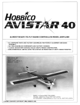
D 66. Check the following: The sketch helps explain it.
A. The rudder moves to the right when the right
transmitter stick is moved to the right (looking at
the plane from the rear).
B. The elevator moves up when the right
transmitter stick is moved down (back).
15

C. The throttle is closed almost all the way when
the left transmitter stick is down (back) and is
open completely when the stick is up (forward).
TRANSMITTER
STICK MOVEMENTS
CONTROL SURFACE
MOVEMENTS
ELEVATOR MOVES UP
RUDDER MOVES RIGHT
CARBURETOR WIDE OPEN
D 67. Check to make sure that the tail control surfaces
are in a neutral (straight) position and the servo arms are
perpendicular to the aluminum channel when the
transmitter sticks at neutral. Also check the control
throws on the tail surface. You should be able to move
the rudder 3/4" both directions and the elevator should
move 1/2" both directions. This should give you a plane
that is fairly responsive but not too radical.
D 68. Install the second nylon tie wrap around the
aluminum channel and the pushrods right in front of
the tail surfaces. This will help keep the control
surfaces from fluttering.
BALANCING
D 69. With the wing rubber banded to the fuselage, the
fuel tank empty, and everything else in its place, lift the
model by placing one finger tip on the bottom of each
wing at the approximate location of each end of the wing
joiner which is 3" back from the leading edge. The
STURDY BIRDY should hang just slightly nose down
or level. If the plane hangs with the nose pointing up
then you will need to add some weight to the nose of the
plane. There are several ways you can add this weight
including stuffing lead weight around the fuel tank or
using one of the heavy prop nuts available. Under no
circumstance should you try to fly the plane if it does
not balance correctly!
GETTING READY FOR FLYING
D 70. Use at least four rubber bands to hold the
engine/firewall in place and use eight #64 rubber bands
to hold the wing in place.
D 71. We recommend that you use a nylon propeller for
your first flights since it will not break as easily as wood.
Sand the edges of the prop before you use it. The edges
of nylon props are very sharp and should be dulled
before use. If a prop is damaged in any way it should be
discarded and a new prop used in its place.
D 72. Be sure to conduct a range test on your radio
system before every flying session. The instruction
manual that came with your radio should explain how
to properly do this.
D 73. If you are using a new engine in your plane, break
it in on the ground according to the manufacturer's
instructions before attempting to fly the plane.
D 74. Never try to start the engine by flipping it over
with your finger. Always use either an electric starter or
a "Chicken Stick".
D 75. Always adjust the needle valve on the engine from
the back of the plane. Never reach over a rotating
prop! Treat these engines with the utmost respect, they
are not toys!
D 76. After each flight, check the propeller, engine bolts,
control surfaces, control linkages, hinges and rubber
bands for damage or looseness and correct if necessary.
An ounce of prevention here will keep you happily
flying longer.
FLYING
The STURDY BIRDY is a very stable flying
airplane with a unique self-recovering system designed
into it. This makes it one of the easiest-flying planes
available. However, it is highly recommended that you
consult an experienced pilot to help trim out the plane
and help you with your first flights. The most
important thing to remember when learning to fly is
that you need to be able to relate to the control inputs
as if you were sitting in the plane. If you don't, it will
seem like the rudder is working backwards when the
plane is flying towards you. It may also seem a little
strange that you pull the stick down (back) in order to
make the plane go up, but this is how it works in real
planes. It is a good idea to keep facing the same
direction that the model is flying.
16

The STURDY BIRDY should be hand launched into
the wind for your first flights. Have a helper hold the
plane firmly behind the landing gear with the wings
level while you check the controls. Advance the throttle
to full throttle and your helper should then take a few
running steps and let the plane fly out of his hand with a
slight push (being careful to keep the wings level). A
strong throw is not necessary. Be prepared to make any
initial controls to keep the plane climbing slightly and
flying straight.
Your control inputs should be very gentle until the
plane has climbed high enough to be out of danger of
hitting any ground based objects (especially the
ground). Once you have reached a safe altitude, trim
the plane for straight and level flight with the engine
running about half throttle. If you get disoriented or
the plane does not seem to be doing what you think it
should, just release the control sticks and the plane
will right itself. If you see that the plane is heading for
danger which you can not prevent, reduce the throttle
to idle and pull the elevator stick back (up elevator) to
reduce the impact speed.
When the plane banks into a turn it is normal for the
nose to drop down so be prepared to put in a little up
elevator to keep it flying level.
Once you are familiar with how the STURDY
BIRDY handles under power, pull the throttle back to
near idle and slow the plane down. Be sure to do this at a
safe altitude! Feed in up elevator to try to keep the plane
flying at the same altitude. If the plane stalls (falls off to
one side abruptly) just release the control sticks, advance
the throttle to at least 1/2 and gently pull in some up
elevator. Try to determine the slowest speed the plane
will fly at and remember that you need to stay above that
speed when landing and taking off to avoid a stall.
If you find the plane getting too high and it is hard to
determine what it is doing, reduce the throttle to idle and
be patient. The STURDY BIRDY will lose altitude
fairly quickly and you can resume control.
When preparing to land it is a good idea to make
several practice passes from a safe altitude and gradually
get lower until you feel comfortable with your approach.
Then on one of your next passes, just decrease the
throttle and the plane will land by itself. Landing is
really not very tricky if you just concentrate on guiding
the plane with the rudder where you want it to go and let
it settle to the ground. Of course it helps to fly at a field
that is big enough so you don't have to worry about
where you need to land.
The STURDY BIRDY also handles very nicely on
the ground despite the fact that it is a tail dragger without
a steerable tail wheel. When taxiing in grass, hold in up
elevator until the plane is moving pretty well to help
keep it from nosing over. To steer the model when it is
moving slow, throw in full rudder and use bursts of
throttle to move the plane around.
REPAIRING
The STURDY BIRDY is very tough, but there may
be crashes hard enough to break parts of the plane.
The fuselage should not be repaired. It is inexpensive
and very easy and quick to replace. Due to the nature of
plastics it is very hard to properly mend if cracked or
broken and should be replaced for safety's sake.
The foam wing will really take a beating and
survive. Small dents and dings can be removed by
patching or re-heating the covering material. A broken
wing can be quickly repaired with epoxy, but check the
nylon tape and replace it if needed. If the wings get
bent you can straighten them by bending them the
opposite direction and adding a couple more strips of
strapping tape. It is important that the wings are kept in
their original configuration with the molded-in washout
(wing twist). This gives the STURDY BIRDY it's
exceptional recovery characteristics.
The tail surfaces can be repaired with C/A glues, or
new surfaces can be cut from 1/4" balsa available from
your local hobby shop.
If dirt gets into the carburetor or onto the engine it
should be cleaned off before it has a chance to get inside
the engine and cause damage.
17

Pilots
Log
Use this to record your flights, it's fun to look back on!
Date
Flight Time
Conditions
Comments
18

Date
Flight Time
Conditions Comments
Engine Mount Template for 20-48 Adjustable Mount
19

WITH AILERONS
1. Locate the two 15/32" x 3/8 x 26-1/2" Sub Trailing Edge pieces (Sub
T.E.). Trial fit the Sub T.E. against the trailing edge of each wing half.
The Sub T.E. should be oriented as shown in the sketch with the 90
degree corners along the bottom of the wing. Epoxy the Sub T.E. to
the
trailing edge
of
each
wing
half
.
Pins or tape can be used to help hold
the Sub T.E. in place while the glue cures.
/