Page is loading ...

INSTALLATION GUIDE
714/715
Zone Expansion Module

714/715 Installation Guide | Digital Monitoring Products 1
GET STARTED
714 and 715 zone expander modules allow you to increase the number of reporting zones available on DMP panels.
The modules connect to the panel Keypad Bus or LX‑Bus and are set to an address that determines the reporting
zone number.
The 714 provides four 5VDC Class B, Style A zones for use with burglary and non‑powered fire devices.
The 715 provides four 12VDC Class B zones for use with burglary, non‑powered, or powered fire devices.
What’s Included
▶One 714 Zone Expansion Module or One 715 Zone Expansion Module
▶(714) Four 1K Ohm Resistors
▶(715) Four 3.3K Resistors
▶12‑Wire Harness
▶Hardware Pack
Compatibility
▶XT30/XT50 Panels
▶XR150/XR550 Panels
INSTALLATION
1 Program the Panel
Program the zones on 714 or 715 zone expander modules with any of the panel’s burglary or fire zone types.
You can also program zones as an Arming zone type when they are being used with key switches. For more
information, refer to the appropriate panel programming guide.
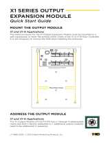
2 Mount the Module
The714/715comes in a high‑impact plastic housing that you
can mount directly to a wall, backboard, or other flat surface.
For easy installation, the housing base contains holes that allow
you to mount themodule on a single‑gang switch box or ring.
Mount the module outside the panel enclosure.
1. Remove the housing fastener screws and separate the
top housing from the base.
2. Insert screws through the desired mounting holes on
the housing base. Refer to Figure 1 for mounting hole
locations.
3. Tighten the screws into place.
4. After wiring and addressing the module, attach the
housing top to the mounted base with the housing
fastener screws. Refer to Figure 2.
Mounting
holes
Housing Base
Housing
fastener
hole
Housing
fastener
hole
Figure 1: Mounting Hole Locations
Figure 2: Screw Locations

714/715 Installation Guide | Digital Monitoring Products 2
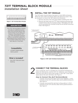
Wire the Module
Connect the 714 to the LX-Bus
To wire the 714, join the red, yellow, green,
and black wires to a 4‑wire harness and
connect it to the LX‑Bus.
Connect the 714 to the Keypad Bus
1. Connect the red, yellow, green, and
black wires to panel Terminals 7, 8, 9,
and 10 respectively.
2. Observe polarity and wire zones 1‑4.
3. Install the included 1K Ohm EOL
resistors.
Connect the 715 to the LX-Bus
To wire the 715, connect the red wire to panel Terminal 11 (Smoke power terminal). This allows Sensor Reset to
drop power to the module and devices connected to its zones. Join the yellow, green, and black wires to a 4‑wire
harness and connect it to the LX‑Bus.
Connect the 715 to the Keypad Bus
1. Connect the red wire to panel Terminal 11 (Smoke power terminal). This allows Sensor Reset to drop power
to the module and devices connected to its zones. Alternately, connect red to a regulated, power limited
power supply listed for Fire Protective Signaling through a Model 716 relay. Use the Sensor Reset Output
programming to drop power to the 715 module.
2. Connect the yellow, green, and black wires to panel Terminals 8, 9, and 10 respectively.
3. Observe polarity and wire zones 1‑4.
4. Install the included 3.3K Ohm EOL resistors.
3
714
Module
Black
Green
Yellow
Red
714 Module:
Connect Red to LX-Bus Wire or Panel Terminal 7
715 Module:
Connect Red to Panel Terminal 11 or a
regulated, power limited power supply listed for
Fire Protective Signaling through a Model 716 relay
+
–
+
–
+
–
+
–
To Keypad Bus or LX-Bus
0
1
2
3
4
5
6
7
8
9
S2
0
1
2
3
4
5
6
7
8
9
S1
TENS ONES
White/Brown: Zone 1
White/Red: Zone 2
White/Orange: Zone 3
White/Yellow: Zone 4
A
B
AB
Figure 3: Module Wiring
SPECIFICATIONS 714 MODULE 715 MODULE
Normal Operating Range 650‑2100 Ohms 1200‑6000 Ohms
Zone Resistors 1k Ohm EOL 3.3k Ohm EOL
Max Line Impedence 100 Ohms 100 Ohms
Zone Ground Fault 1500 Ohms or less 80 Ohms or less
Zone Supervision All Zones All Zones
Table 1: 714 and 715 Modules Specifications

714/715 Installation Guide | Digital Monitoring Products 3
4
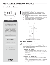
Set the Module Address
714 and 715 Zone Expansion Modules use two rotary switches (TENS and ONES) to set the module address. For
keypad bus addresses, set the switches to match the device address. For LX‑Bus addresses, set the switches to
match the last two digits of the addresses. For example, for address 02 set the switches to TENS 0 and ONES 2 as
shown in Figure 4. For more information, refer to Table 2 and Table 3.
SWITCH XR150 SERIES XR550 SERIES
TENS ONES LX500 LX500 LX600 LX700 LX800 LX900
0 0 500 500 600 700 800 900
0 1 501 501 601 701 801 901
0 2 502 502 602 702 802 902
0 3 503 503 603 703 803 903
0 4 504 504 604 704 804 904
... ... ... ... ... ... ... ...
9 5 595 595 695 795 895 995
9 6 596 596 696 796 896 996
9 7 597 597 697 797 897 997
9 8 598 598 698 798 898 998
9 9 599 599 699 799 899 999
Table 2: Lx-Bus Addresses and Corresponding Zone Numbers
KEYPAD BUS ADDRESS
SWITCH ZONE NUMBERS
TENS ONES XT30/XT50 AND XR150 SERIES XR550 SERIES
1 0 1 11 to 14 11 to 14
2 0 2 21 to 24 21 to 24
3 0 3 31 to 34 31 to 34
4 0 4 41 to 44 41 to 44
5 0 5 51 to 54 51 to 54
6 0 6 61 to 64 61 to 64
7 0 7 71 to 74 71 to 74
8 0 8 81 to 84 81 to 84
9 0 9 N/A 91 to 94
10 1 0 N /A 101 to 104
11 1 1 N/A 111 to 114
12 1 2 N /A 121 to 124
13 1 3 N/A 131 to 134
14 1 4 N /A 141 to 144
15 1 5 N/A 151 to 154
16 1 6 N/A 161 to 164
Table 3: Keypad Bus Addresses and Corresponding Zone Numbers

714/715 Installation Guide | Digital Monitoring Products 4
ADDITIONAL INFORMATION
Wiring Specifications
DMP recommends using 18 or 22 AWG for all LX‑Bus and Keypad Bus connections. The maximum wire distance
between any module and the DMP Keypad Bus or LX‑Bus circuit is 1,000 feet. To increase the wiring distance, install
an auxiliary power supply, such as a DMP Model 505‑12. Maximum voltage drop between a panel or auxiliary power
supply and any device is 2.0 VDC. If the voltage at any device is less than the required level, add an auxiliary power
supply at the end of the circuit.
To maintain auxiliary power integrity when using 22‑gauge wire on Keypad Bus circuits, do not exceed 500 feet.
When using 18‑gauge wire, do not exceed 1,000 feet. Maximum distance for any bus circuit is 2,500 feet regardless of
wire gauge. Each 2,500 foot bus circuit supports a maximum of 40 LX‑Bus devices.
For additional information refer to the following documents:
▶ LX‑Bus/Keypad Bus Wiring Application Note (LT‑2031)
▶ 710 Bus Splitter/Repeater Module Installation Guide (LT‑0310)
Optional Accessories
You can replace the standard wiring harness with the optional 718T Plug‑in Screw Terminal. The enclosure base can
also accommodate the 719T Terminal Boards for the 714 or the 720T Terminal Boards for the 715, both of which pass
through panel LX‑Bus wiring. The 719T includes 1k EOL resistors. The 720T includes 3.3k EOL resistors.
LED Operation
The LED on the zone expanders flashes each time the module responds to a poll from the panel. If there is a problem
with the hardware, panel programming, or the green data wire between the panel and the zone expander module, the
LED stops flashing and System Trouble appears in the keypad display.
COMPLIANCE INFORMATION
UL Commercial Burglary
To comply with ANSI/UL 365 Police‑Connected Burglary System or ANSI/UL 609 Local Burglary Alarm Systems, the
module must be mounted in the supplied, UL listed enclosure with a tamper.
UL Commercial Fire
See the panel installation guide for details for selecting compatible 2‑wire smoke detectors. Any auxiliary power
supply used must be regulated, power limited and listed for Fire Protective Signaling.
ULC Commercial Burglary (XR150/XR550 Series Panels)
Place the zone expander module in a listed enclosure and connect a DMP Model 307 Clip‑on Tamper Switch to the
enclosure programmed as a 24‑hour zone.
The 714/715 zones can be installed in medium or high risk applications when two zones are used as shown in the Dual
Zone Protection diagram in the XR150/XR550 Canadian Installation Guide. Otherwise, 714/715 zones can only be used
in low risk applications.
ULC Residential Fire (XR150/XR550 Series Panels)
Refer to the appropriate panel compliance listing guide for the complete list of UL approved smoke detectors.

18205
Designed, engineered, and
manufactured in Springfield, MO
using U.S. and global components.
LT-0161 1.06 21344
INTRUSION • FIRE • ACCESS • NETWORKS
2500 North Partnership Boulevard
Springfield, Missouri 65803-8877
800.641.4282 | DMP.com
© 2021
SPECIFICATIONS
Operating Voltage 12VDC
714 Operating Current 7mA + 1.6mA per zone
714 Zone Voltage 5VDC, max 2mA
715 Operating Current 7mA + 4mA per active zone
+ 30mA per smoke in alarm
+ 58mA per zone shorted
715 Zone Voltage 12VDC, max 58mA
Dimensions 4.50 W x 2.75 H x 1.75 D in
11.43 W x 6.99 H x 4.45 D cm
Zones 4 Supervised Class B Style A Power Limited
CERTIFICATIONS
▶California State Fire Marshal (CSFM)
Underwriters Laboratory (UL) Listed
ANSI/UL 365 Police Station Connect Burglar Alarm Systems
ANSI/UL 609 Local Burglar Alarm Units & Systems
ANSI/UL 864 Fire Protective Signaling Systems
ANSI/UL 985 Household Fire Warning System Units
ANSI/UL 1023 Household Burglar Alarm System Units
ANSI/UL 1076 Proprietary Burglar Alarm Units & Systems
ANSI/UL 1610 Central Station Burglar Alarm Units
ANSI/UL 1635 Digital Alarm Communication System Units
ULC Subject‑C1023 Household Burglar
ULC/ORD‑C1076 Proprietary Burglar
ULC S304 Central Station Burglar
ULC S545 Household Fire
/