Page is loading ...

712-8-3.3K ZONE EXPANSION MODULE
Installation Guide
DESCRIPTION
MODEL
712-8-3.3K
The Model 712-8-3.3K Zone
Expansion Module allows you to
increase the number of protection
zones available on a DMP panel. The
712-8-3.3K provides a total of eight
grounded zones.
The zone expansion module
provides a terminal strip for zone
inputs, two 4-pin headers for
Keypad Bus or LX-Bus connections,
a jumper for LX-Bus or Keypad Bus
operation, and a transmit data LED
to indicate panel communication.
Note: The 712-8-3.3K is listed for
use in burglary applications only:
No fire circuits shall be used on this
device.
Compatibility
• XT30/XT50 Series panels
• XR150/XR550 Series panels
What is Included?
• One 712-8-3.3K Zone Expansion
Module
• Eight 3.3K Ohm EOL Resistors
• Hardware pack
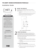
1MOUNT THE MODULE
Themodule can be mounted in a DMP enclosure using the
standard3-hole mounting pattern. Refer to Figure 2as needed
during installation.
1. Hold the plastic standos against the inside of the enclosure
side wall.
2. Insert the included Phillips head screws from the outside of
the enclosure into the standos. Tighten the screws.
3. Carefully snap the module onto the standos.
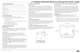
WIRE THE MODULE
2Use18to22gauge wire to connect the712-8-3.3K directly to
the Keypad Bus or use a dual-ended4-wire harness to connect
directly to the LX-Bus. This connection allows the module to
communicate with the panel and receive12VDC power. DMP
recommends a2,500foot maximum wiring distance. For more
information about wiring specifications, refer to Additional
Information. Refer to Figure 3when wiring themodule.
Connect to the LX‑Bus
1. Place a jumper across the top two KEYPAD/LX- BUS pins.
2. Connect one end of a4-wire harness to the top header on
the module.
3. At the panel, connect the other end of the4-wire harness
to the LX-Bus.
Connect to the Keypad Bus
1. Place a jumper across the bottom two KEYPAD/LX- BUS
pins.
2. Connect a4-wire harness to thetop header on the module.
3. At the panel, connect the wires to the corresponding
Keypad Bus terminals.
Figure 1: 712-8-3.3k
Figure 2: Stando and Module Installation
BACK
1
2
3

2 712-8-3.3K INSTALLATION GUIDE | DIGITAL MONITORING PRODUCTS
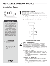
3To communicate the status of the eight zones, the
module responds to two addresses on the Keypad
Bus and eight addresses on the LX-Bus. You can set
the module starting address to any bus address from
0to 15. The module automatically responds to this
address, the next address on the Keypad Bus, and the
next seven addresses on the LX-Bus.
To change the current address, move the slide
switches to the appropriate address positions
according to Figure 4.
Keypad Bus Addressing
The module can be set to the following keypad
addresses according to panel model: 1through 8for
XT30/XT50 and XR150 Series panels, or1through
15for XR550Series panels. Additionally, the eight
zones on the module occupy two keypad addresses.
For example, if the module is set to address2, the first four expansion zones occupy address 2and respond
as zones 21-24. The last four expansion zones occupy address 3and respond to the panel as zones 31-34. For
more information about Keypad Bus addressing, refer to Table1.
Note: Because the 712-8-3.3K is supervised, both addresses must be selected in Device Setup of the
XR150/XR550Series programming when used on the Keypad Bus.
LX‑Bus Addressing
When connecting to the LX-Bus, the module must be addressed to match the last two digits of the
first zone being used. The next seven zone addresses are automatically used to communicate expander
zones2through8status.
For example, on an XR150panel using LX-Bus 1if you set the module address to8, the eight zones on the
expander respond as zones 508to 515. When connected to an XR550panel using LX-Bus 2, the zones respond
as 608to 615. For more information about LX-Bus addressing, refer to Table2.
Note: Only two 712-8-3.3K Modules can be connected to each LX-Bus.
ADDRESS THE MODULE
Z1 Z2 Z3 Z4 Z5 Z6 Z7 Z8GND GND GND GND
TXD
BLK
BLK
RED
RED
712-8-3.3K
AC
1234 5 6 7 810 11 12 13 14 15 16 17 18
9
+B BELL GND SMK GND
RED YEL GRN BLK Z1 Z2 Z3 Z4 Z5
20
Z6
AC -B GND
19
GND
21
Z7
22
GND
23
Z8
24
Z9
25
Z10+
26
Z10-
RED
PROG
XT30
To other zone
expansion modules
on the same bus.
3.3K EOL 3.3K EOL
3.3K EOL
3.3K EOL
3.3K EOL
3.3K EOL
3.3K EOL
3.3K EOL Zone 1
Zone 2
Zone 3
Zone 4
Zone 8
Zone 7
Zone 6
Zone 5
Use supplied 3.3K EOL resistors on each zone.
Normal operating range is 650-1200 Ohms
These 4-pin headers are connected
together internally to allow bus
connection of other zone expansion
modules.
ADDRESS KEYPAD
LX-BUS
Figure 3: Wiring Diagram
1 2 3 4
5 6 7 8
9 10 11 12
13 14 15 16
ON
1 2 3 4
ON
1 2 3 4
ON
1 2 3 4
ON
1 2 3 4
ON
1 2 3 4
ON
1 2 3 4
ON
1 2 3 4
ON
1 2 3 4
ON
1 2 3 4
ON
1 2 3 4
ON
1 2 3 4
ON
1 2 3 4
ON
1 2 3 4
ON
1 2 3 4
ON
1 2 3 4
ON
1 2 3 4
Figure 4: Addressing the Module

712-8-3.3K INSTALLATION GUIDE | DIGITAL MONITORING PRODUCTS 3
ADDITIONAL INFORMATION
Wiring Specifications
DMP recommends using 18 or 22 AWG for all LX-Bus and Keypad Bus connections. The maximum wire distance between
any module and the DMP Keypad Bus or LX-Bus circuit is 10 feet. To increase the wiring distance, install an auxiliary
power supply, such as a DMP Model 505-12. Maximum voltage drop between a panel or auxiliary power supply and any
device is 2.0 VDC. If the voltage at any device is less than the required level, add an auxiliary power supply at the end of
the circuit.
To maintain auxiliary power integrity when using 22-gauge wire on Keypad Bus circuits, do not exceed 500 feet. When
using 18-gauge wire, do not exceed 1,000 feet. Maximum distance for any bus circuit is 2,500 feet regardless of wire
gauge. Each 2,500 foot bus circuit supports a maximum of 40 LX-Bus devices.
For additional information refer to the LX-Bus/Keypad Bus Wiring Application Note (LT-2031) and the 710 Bus Splitter/
Repeater Module Installation Guide (LT-0310).
Data LED
The LED on the 712-8-3.3K flashes each time the module responds to a poll from the panel. If there is a problem with
the panel, system programming, or the connection between the panel and module, the LED stops flashing and a system
trouble message displays on the keypad.
UL Commercial Burglary
The 712-8-3.3K Zone Expansion Module must be mounted inside the control unit enclosure or other Listed enclosure.
DMP PANEL
KEYPAD BUS
712-8 3.3K
ADDRESS
EXPANDER ZONES
1-4 5-8
PANEL ZONES
XT30/XT50 Series,
XR150/XR550
Series
1 11-14 21-24
2 21-24 31-34
3 31-34 41-44
4 41-44 51-54
XT30/XT50 Series,
XR150/XR550
Series
5 51-54 61-64
6 61-64 71-74
771-74 81-84
8 81-84 91-94
XR550 Series
9 91-94 101-104
10 101-104 111-114
11 111-114 121-124
12 121-124 131-134
13 131-134 141-144
14 141-144 151-154
15 151-154 161-164
712-8 3.3K
ADDRESS
XR150/XR550 SERIES LX-BUS
PANEL ZONE RANGE
LX-BUS 1 LX-BUS 2 LX-BUS 3 LX-BUS 4 LX-BUS 5
0 500-507 600-607 700-707 800-807 900-907
1 501-508 601-608 701-708 801-808 901-908
2 502-509 602-609 702-709 802-809 902-909
... ... ... ... ... ...
7 507-514 607-614 707-714 807-814 907-914
8 508-515 608-615 708-715 808-815 908-915
9 509-516 609-616 709-716 809-816 909-916
... ... ... ... ... ...
12 512-519 612-619 712-719 812-819 912-919
13 513-520 613-620 713-720 813-820 913-920
14 514-521 614-621 714-721 814-821 914-921
15 515-522 615-622 715-722 815-822 915-922
Table 1: Keypad Bus Addresses
Table 2: LX-Bus Addresses

Designed, engineered, and
manufactured in Springfield, MO
using U.S. and global components.
LT-1152 1.02 20021
712-8-3.3K ZONE
EXPANSION MODULE
Specifications
Operating Voltage 8.0 to 14.5VDC
Current Draw
Normal 17mA + 1.6mA per active zone
Alarm 17mA + 2.0mA per active zone
Dimensions 4.50” W x 2.50” H
11.43 cm W x 5.08 cm H
Weight 8.0oz (23.0 kg)
Compatibility
XT30/XT50 Series Panels
XR150/XR550 Series Panels
Certifications
FCC Part 15
Underwriters Laboratory (UL) Listed
ANSI/UL 365 Police Station Connected Burglar
ANSI/UL 609 Local Burglar Alarm Unites and
Systems
ANSI/UL 1023 Household Burglar Alarm System
Units
ANSI/UL 1076 Proprietary Burglar Alarm Units
ANSI/UL 1610 Central Station Burglar Alarm Units
ANSI/UL 1635 Digital Burglary
MODEL
712-8-3.3K
INTRUSION • FIRE • ACCESS • NETWORKS
2500 North Partnership Boulevard
Springfield, Missouri 65803-8877
800.641.4282 | DMP.com
FCC INFORMATION
This device complies with Part 15 of the FCC Rules. Operation is subject to the following two conditions:
1. This device may not cause harmful interference, and
2. this device must accept any interference received, including interference that may cause undesired operation.
The antenna used for this transmitter must be installed to provide a separation distance of at least 20 cm (7.874 in.) from
all persons. It must not be located or operated in conjunction with any other antenna or transmitter.
Changes or modifications made by the user and not expressly approved by the party responsible for compliance could
void the user’s authority to operate the equipment.
Note: This equipment has been tested and found to comply with the limits for a Class B digital device, pursuant to
part 15 of the FCC Rules. These limits are designed to provide reasonable protection against harmful interference in
a residential installation. This equipment generates, uses and can radiate radio frequency energy and, if not installed
and used in accordance with the instructions, may cause harmful interference to radio communications. However,
there is no guarantee that interference will not occur in a particular installation. If this equipment does cause
harmful interference to radio or television reception, which can be determined by turning the equipment o and on,
the user is encouraged to try to correct the interference by one or more of the following measures:
1. Reorient or relocate the receiving antenna.
2. Increase the separation between the equipment and receiver.
3. Connect the equipment into an outlet on a circuit dierent from that to which the receiver is connected.
4. Consult the dealer or an experienced radio/TV technician for help.
/