Page is loading ...

X1 SERIES OUTPUT
EXPANSION MODULE
Quick Start Guide
LT-2468 21293 © 2021 Digital Monitoring Products, Inc.
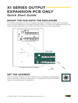
MOUNT THE OUTPUT MODULE
X1 and X1-8 Applications
The metal enclosure for the X1 Output Expansion Module must be mounted to a
wall, backboard, or other flat surface within 3 feet of the X1 or X1-8 Door Controller.
It is not necessary to remove the PCB when installing the enclosure.
X1 Door Controller
12 V Battery
+ -
-
+
0
1
2
3
4
5
6
7
8
9
Output Expansion Module
Mounting Holes
0
1
2
3
4
5
6
7
8
9
Output Expansion ModuleX1 Door Controller
12 V Battery
+ -
-
+
ADDRESS THE OUTPUT MODULE
X1 and X1-8 Applications
The X1 Output Module (X1-OUT-EXP) has a 1 through 9 addressable
rotary dial that is factory defaulted to 1. Additional output modules
need to be addressed in sequence.

X1 OUTPUT MODULE EXPANSION QUICK START GUIDE | DIGITAL MONITORING PRODUCTS 2
WIRE THE OUTPUT MODULE
X1 Applications
Use the included 4-position harness to connect the top connector on the second
output module to the connector on the first output module.
0
1
2
3
4
5
6
7
8
9
Output Expansion ModuleX1 Door Controller
12 V Battery
+ -
-
+

3 X1 OUTPUT MODULE EXPANSION QUICK START GUIDE | DIGITAL MONITORING PRODUCTS
X1-8 Applications
Use the included 4-position harness to connect the top connector on the second
output module to the connector on the first output module.
Output Expansion Module 1:
Address 1
100 VAC Wire-In
Transformer
0
1
2
3
4
5
6
7
8
9
0
1
2
3
4
5
6
7
8
9
0
1
2
3
4
5
6
7
8
9
0
1
2
3
4
5
6
7
8
9
0
1
2
3
4
5
6
7
8
9
0
1
2
3
4
5
6
7
8
9
0
1
2
3
4
5
6
7
8
9
Door Controller: Preset Address 1
Module 1: Address 2
Module 2: Address 3
Module 3: Address 4
Module 4: Address 5 Module 5: Address 6
Module 6: Address 7
Module 7: Address 8
Model 505-12
0
1
2
3
4
5
6
7
8
9
0
1
2
3
4
5
6
7
8
9
0
1
2
3
4
5
6
7
8
9
0
1
2
3
4
5
6
7
8
9
0
1
2
3
4
5
6
7
8
9
0
1
2
3
4
5
6
7
8
9
0
1
2
3
4
5
6
7
8
9
0
1
2
3
4
5
6
7
8
9
-
+
-
+
12 V Battery
+ -
-
+

More Information
Designed, engineered, and manufactured in Springfield, Missouri
.
INTRUSION • FIRE • ACCESS • NETWORKS
2500 North Partnership Boulevard Springfield, Missouri 65803-8877
800.641.4282 | dmp.com
|
PROGRAM IN DEALER ADMIN™
X1 and X1-8 Applications
Go to Dealer Admin (dealer.securecomwireless.com) to program the output
module.
TEST THE CONTROLLER
X1 and X1-8 Applications
Make sure that the Reader LEDs are on and the door controller’s power LED is
on. If connected to Wi-Fi, the Wi-Fi LED is on solid. If connected to network, the
Network Port light is blinking. For cell and all communication methods, check
that the door controller is communicating with Dealer Admin and Virtual Keypad
after Dealer Admin programming is completed.
The output modules each have ten onboard LEDs per output relay. For visual
confirmation of the relay operation, the LEDs are on when the relay is on and o
when the relay is o.
WIRE THE OUTPUT MODULE
X1 and X1-8 Applications
To wire for output control, use the 10
terminals on the output module.
The X1 Series Output Module provides
10 Form C (SPDT) 1 Amp relays for 10
outputs. The three relay terminals are
labeled for normally open (NO) and
normally closed (NC) operation. The
center terminal is the common.
PWR
DATA
0
1
2
3
4
5
6
7
8
9
ADDR
6
1
7 8 9 10
2 3 4 5
NC 1 NO NC 2 NO NC 3 NO NC 4 NO NC 5 NO
NC 6 NO NC 7 NO NC 8 NO NC 9 NO NC 10 NO
NC 1 NO NC 1 NO
Normally Open Normally Closed
X1 Output Expansion Module
NC 1 NO
Normally Open
Common
Normally Closed
Follow the QR code for the full Installation and
Programming Guide.
/