Page is loading ...

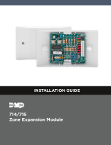
INSTALLATION GUIDE
711
Zone Expander Module

711 Installation Guide | Digital Monitoring Products 1
GET STARTED
Zone expander modules allow you to increase the number of reporting zones available on DMP panels. Refer to the
panel installation guide for more information about zone expansion modules and the maximum number allowed per
panel. The modules connect to the panel 4-wire Keypad Bus or LX-Bus™ and are set to an address that determines the
reporting zone number. The 711 provides one Type A Class B zone.
The 711 housing mounts to any flat surface using the mounting holes provided in the base. Snap on the cover to
complete the installation.
What’s Included
▶711 Expander Module
▶1k Ohm Resistor
Compatibility
▶XT30/XT50 and XR150/XR550 Series Panels
PCB Layout
Red
Yellow
Green
Black
Positive
Negative
ONES
TENS

711 Installation Guide | Digital Monitoring Products 2
INSTALLATION
1 Address the Module
The 711 Zone Expander uses two rotary switches identified as TENS and ONES to set
the module address. See LX-Bus Zone Numbers below for LX-Bus addresses and set
the switches to match the last two digits of the address. For example, for address 502
on an XR550 Series panel set the TENS switch to zero and the ONES switch to two.
Keypad Bus Zone Numbers
The 711 module uses zone 1 only. The last three zone numbers cannot be used for other devices. For example, turn
the 711 switches to address 02 (TENS = 0, ONES = 2) to set the module zone number to zone 21. Zones 22, 23, and
24 cannot be used.
0
1
2
3
4
5
6
7
8
9
0
1
2
3
4
5
6
7
8
9
T
E
N
S
O
N
E
S
KEYPAD ADDRESS SWITCHES ZONE NUMBER
TENS ONES XT30/50 XR150 XR550
1 0 1 11 11 11
2 0 2 21 21 21
3 0 3 31 31 31
4 0 4 41 41 41
5 0 5 51 51 51
6 0 6 61 61 61
7 0 7 71 71 71
8 0 8 81 81 81
9 0 9 N /A N/A 91
10 1 0 N/A N/A 101
11 1 1 N/A N /A 111
12 1 2 N/A N /A 121
13 1 3 N/A N /A 131
14 1 4 N/A N /A 141
15 1 5 N/A N /A 151
16 1 6 N /A N/A 161
Table 1: Keypad Bus Zone Numbers

711 Installation Guide | Digital Monitoring Products 3
2 Install the Module
Wiring the 711 Module
Connect the Red, Green, Yellow, and Black wires from the panel Keypad Bus or LX-Bus™ to the matching terminals
or harness wires on the zone expander.
Caution: Do not use looped wire under terminals. Break wire run to provide supervision of connections.
Wiring Specifications for Keypad and LX-Bus
DMP recommends using 18 or 22 gauge unshielded wire for all keypad and LX-Bus circuits. Do not use twisted
pair or shielded wire for LX-Bus and Keypad Bus data circuits. To maintain auxiliary power integrity when using
22-gauge wire do not exceed 500 feet. When using 18-gauge wire do not exceed 1,000 feet. Install an additional
power supply to increase the wire length or add devices.
Maximum distance for any one circuit (length of wire) is 2,500 feet despite the wire gauge or number of branches.
Increased wire distance from the panel decreases DC voltage on the wire. Maximum number of devices per 2,500
feet circuit is 40.
Note: Each panel allows a specific number of supervised keypads. Add additional keypads in the
unsupervised mode. Refer to the panel installation guide for the specific number of supervised keypads
allowed.
Maximum voltage drop between the panel (or auxiliary power supply) and any device is 2.0 VDC. If the voltage at
any device is less than the required level, add an auxiliary power supply at the end of the circuit. When voltage is
too low, the devices cannot operate properly.
Refer to the panel installation guide and LX-Bus/Keypad Bus Wiring Application Note (LT-2031). Also see the 710
Module Installation Sheet (LT-0310) for more information.
LX-Bus Zone Numbers
Refer to Table 1 for a partial list of XR550 Series panel LX-Bus zone numbers. XR150 Series panels only use LX-
Bus 1 (LX500).
Table 1: LX-Bus Zones Numbers
LX-BUS ADDRESS LX-BUS NUMBER SWITCHES ZONE NUMBER
TENS ONES
501 1 (LX500) 0 1 501
506 1 (LX500) 0 6 506
623 2 (LX600) 2 3 623
654 2 (LX600) 5 4 654
742 3 (LX700) 4 2 742
768 3 (LX700) 6 8 768
833 4 (LX800) 3 3 833
877 4 (LX800) 7 7 877
919 5 (LX900) 1 9 919
994 5 (LX900) 9 4 994

711 Installation Guide | Digital Monitoring Products 4
Program the Module
You can program the zone expander module zone with any panel Burglary or Fire zone type or as an Arming type
zone when used with keyswitches.
Zone Expander Data LED
The zone expander LED flashes each time the module responds to a poll from the panel. If there is a problem with
the panel, panel programming, or the green data wire between the panel and the zone expander module, the LED
stops flashing and “System Trouble” appears in the keypad display.
3
0
1
2
3
4
5
6
7
8
9
0
1
2
3
4
5
6
7
8
9
O
N
E
S
T
E
N
S
- +
B G Y R
CR1
Data LED Red
To Panel Keypad Bus or LX-Bus
To Next Module
All wiring is power limited
and supervised
1K Ω EOL
Yellow
Green
Black
Positive (+)
Negative (
–
)
Address
Switches
N/O
N/C
Red
Yellow
Green
Black
Protection Zone Supervised 5 V, Class B, Style A
Max Impedance 100 Ω
Ground Fault Detected < 1200 Ω
Normal Operating Range 650 Ω to 1200 Ω
COMPLIANCE INFORMATION
UL
To comply with ANSI/UL 365 Police-Connected Burglary System or ANSI/UL 609 Local Burglary Alarm Systems, the
module must be mounted in a listed enclosure with a tamper installed. The keypad and LX-Bus are rated Class B, Style 3.5.
ULC Commercial Burglary
XR100/XR500 & XR150/XR350/XR550 Series panels
Place the 711 and other zone expander modules in a listed enclosure and connect a DMP Model 307 Clip-on Tamper
Switch to the enclosure programmed as a 24-Hour zone.
The 711 zone can only be used in Low Risk applications. Medium or High Risk applications must use panel zone inputs.

18205
Designed, engineered, and
manufactured in Springfield, MO
using U.S. and global components.
LT-0231 1.05 21344
INTRUSION • FIRE • ACCESS • NETWORKS
2500 North Partnership Boulevard
Springfield, Missouri 65803-8877
800.641.4282 | DMP.com
© 2021
SPECIFICATIONS
Operating Voltage 8.8 to 15.0 VDC
Operating Current
Standby 11 mA (+ 1.6 mA per active zone)
Alarm 11 mA (+ 2 mA per active zone)
Zone Voltage 5 VDC, max 2 mA
EOL Value 1k Ohm
Dimensions 1.25 W x 2.75 H in.
3.18 W x 6.99 H cm.
Wire Specification Accepts 12 to 22 AWG wire
CERTIFICATIONS
▶California State Fire Marshal (CSFM)
▶New York City (FDNY COA #6167)
▶Commercial Burglar and Fire Accessory Zone Expander
▶Signaling Device
Underwriters Laboratory (UL) Listed
ANSI/UL 365 Police Station Connect Burglar Alarm Systems
ANSI/UL 609 Local Burglar Alarm Units & Systems
ANSI/UL 864 Fire Protective Signaling Systems
ANSI/UL 985 Household Fire Warning System Units
ANSI/UL 1023 Household Burglar Alarm System Units
ANSI/UL 1076 Proprietary Burglar Alarm Units & Systems
ANSI/UL 1610 Central Station Burglar Alarm Units
ANSI/UL 1635 Digital Alarm Communication System Units
ULC Subject-C1023 Household Burglar
ULC/ORD-C1076 Proprietary Burglar
ULC S304 Central Station Burglar
ULC S545 Household Fire
/