Page is loading ...

721T TERMINAL BLOCK MODULE
Installation Sheet
DESCRIPTION
Figure 1: 721T Terminal Block Module
The 721T Terminal Block Module
provides an additional panel-
style zone terminal block with
built-in End-of-Line (EOL) 1K
resistors. Mounting the 721T
in or near the panel enclosure
oers a convenient option for
terminating zone connections in
one location rather than at the
zone device in the field.
Compatibility
• All DMP XR150/XR550
Series panels
What is Included?
• One 721T PCB with foam
backing
1INSTALL THE 721T MODULE
The 721T easily mounts below the panel in most DMP enclosures.
When the rear center knockouts below the panel are used, it may
be necessary to mount the 721T below the knockouts.
1. Remove all power from the panel before installing the 721T.
2. Remove the tape from the 721T foam backing and press the
module firmly onto the enclosure back. Alternately, the 721T
can be permanently mounted using the pre-drilled mounting
holes. See Figure 2.
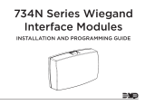
CONNECT THE TERMINAL BLOCKS
2Use 4-conductor wire to complete the connections between the
panel, the field device, and the 721T. For reference, use a marker to
write the zone device name and number on the 721T in the white
space above the zone terminals. See Figure 2.
How to Connect the AUX Terminal Blocks
1. Connect one end of the black wire to the negative (-) AUX
terminal on the 721T and the other end to panel terminal 10.
See Figure 2.
2. Connect one end of the red wire to the positive (+) AUX
terminal on the 721T and the other end to panel terminal 7.
See Figure 2.
Figure 2: 721T AUX Terminal Connections
AC
1 2 3 4 5 6 7 8 10 11 12 13 14 15 16 17 18 199 20 21 22 23 24 25 26 27 28
+B BELLGND SMK GNDRED YEL GRN BLK Z1 Z2 Z3 Z4 Z5 Z6 Z7 Z8 Z9+ Z9– Z10+Z10–AC –B GND GND GNDGND
Battery
Start
PROG XR150 Panel
To Battery
To AC
Predrilled
Mounting Hole
Red
Black
14 AWG Ground Wire
to Earth Ground
AUX
Z7 N/C
Contact Z8 N/O
Contact
Write Zone Device Name
above Zone Number
Terminal Blocks
End-of-Line (EOL) Resistors – One Resistor for each Zone and Bell Circuit

Designed, engineered, and
manufactured in Springfield, MO
using U.S. and global components.
LT-0861 20021
721T TERMINAL BLOCK MODULE
Specifications
Dimensions 7.70” W x 1.65” H x 0.83” D
19.56 cm W x 4.19 cm H x 2.11 cm D
INTRUSION • FIRE • ACCESS • NETWORKS
2500 North Partnership Boulevard
Springfield, Missouri 65803-8877
800-641-4282 | DMP.com
Compatibility
XR150/XR550 Series Panels
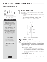
How to Connect N/O Contacts
Follow these steps to connect a N/O (Normally
Open) contact to panel zone 8 in parallel. See
Figure 3.
Note: When a circuit is in parallel, each
component is equal, and the voltage
across the circuit is the sum of the
voltages across each component.
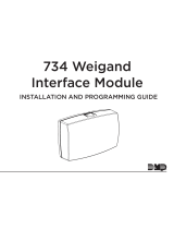
How to Connect N/C Contacts
Follow these steps to connect a N/C (Normally
Closed) contact to panel zone 7 in series. See
Figure 4.
Note: When a circuit is in series, each
component must function to
complete the circuit.
14 15 16 17 18 19 20 21 22 23 24 25 26 27 28
Z2 Z3 Z4 Z5 Z6 Z7 Z8 Z9+ Z9–Z10+Z10–GND GND GNDGND
XR150 Panel
Black
External Zone 7
N/C Contact
Red
Zone 7 1k
EOL Resistor
Z7 N/C
Contact
Z8 N/O
Contact
Green
Yellow
Figure 3: 721T Wired to N/O Device
14 15 16 17 18 19 20 21 22 23 24 25 26 27 28
Z2 Z3 Z4 Z5 Z6 Z7 Z8 Z9+ Z9–Z10+Z10–GND GND GNDGND
XR150 Panel
Zone 8 1k
EOL Resistor
Red
External Zone 8
N/O Contact
Black
Z7 N/C
Contact
Z8 N/O
Contact
Green
Yellow
Figure 4: 721T Wired to N/C Device
1. Connect the red and yellow wires to the
same terminal on the N/O contact.
2. Connect the black and green wires to the
other terminal on the N/O contact.
3. Connect the other end of the black wire to
panel terminal 23 GND.
4. Connect the other end of the red wire to
panel Z8 terminal 24.
5. Connect the other ends of the yellow and
green wires to the Z8 terminals on the 721T.
1 2 3
1 2 3
1. Connect the red wire to one terminal on the
N/C contact.
2. Connect the yellow wire to the other terminal
on the N/C contact.
3. Connect the black and green wires together.
4. Connect the other end of the black wire to
panel terminal 23 GND.
5. Connect the other end of the red wire to
panel Z7 terminal 22.
6. Connect the other ends of the yellow and
green wires to the Z7 terminals on the 721T.
Example: In Parallel Circuit
Example: In Series Circuit
/